3 INSTALLATION
An MPH2™ Rack PDU can be installed on the frame members of a rack enclosure using factory-supplied
hardware. The unit can be installed on the face or the side of frame members. The unit can be mounted so
that the power cord exits either the top or bottom of the rack enclosure.
NOTE: Follow all local and national electrical codes, standards and recommended practices.
Disconnect Required for Hard-Wired MPH2™ Rack PDU Units
A readily-accessible input-power disconnect device must be installed near the MPH2™ Rack PDU.
Input Power Location for MPH2™ Rack PDU Units with Factory-Installed Power Cords
The input-power socket must be installed near the MPH2™ Rack PDU and must be easily accessible.
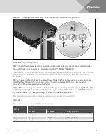
3.1 Attaching Input Power Cords—Hard-wired Models Only
Units with hard-wired input power require attachment of input-power cords. See
Hard-wired models—
Recommended Wiring Sizes
on page 15 for wire sizing.
Hard-wired models may be wired with or without conduit.
3.1.1 Attaching Input-power Cords without Conduit
WARNING! Always verify circuits are de-energized before working with exposed conductors.
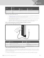
1. Remove the end cap. It is held in place with two T10 Torx screws.
2. Remove the terminal block cover.
3. Loosen the strain-relief collar. It is held in place with two Phillips head PH1 screws.
4. Remove a section of the outer jacket and strip the insulation from the individual wires as
required to fit into the terminal block.
Recommended stripping length for MPH2™ Rack PDU units rated less than 32 A is 9 mm; for
MPH2™ Rack PDUs rated at 40 A or higher, an 11 mm strip length is recommended.
5. Slip the power cord through the hole in the end cap and through the strain-relief collar.
6. Loosen the terminal block screws.
7. Insert the wires into the terminal block according to the labeling inside the MPH2™ Rack PDU;
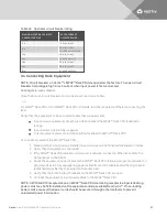
tighten each terminal block screw after inserting a wire. Refer to
Terminal tightening torque
on
page 16 for tightening torque.
8. Tighten the strain-relief collar around the input power cord. The cord’s outer insulation jacket
should extend through the bracket.
9. Replace the terminal block cover by either sliding it on or snapping it into place.
10. Reattach the end cap to the MPH2™ Rack PDU with the two screws removed in step 1.
Vertiv
| Vertiv™ MPH2 Rack PDU Installer/User Guide
13
Summary of Contents for MPH2
Page 1: ...Vertiv MPH2 Rack PDU Installer User Guide ...
Page 16: ...Vertiv Vertiv MPH2 Rack PDU Installer User Guide 12 This page intentionally left blank ...
Page 42: ...Vertiv Vertiv MPH2 Rack PDU Installer User Guide 38 This page intentionally left blank ...
Page 48: ...Vertiv Vertiv MPH2 Rack PDU Installer User Guide 44 This page intentionally left blank ...
Page 49: ......


