For
m
N
o.
: D
PN
00
1040_R
EV
4
REV : 0
REV DATE : 2/19
DPN004931
Page :1 /1
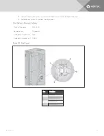
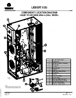
COMPONENT LOCATION DIAGRAM
LIQUID TO AIR 60kW, 600mm (24in.) MODEL
LIEBERT XDU
1
13
12
8
2
3
4
5
6
7
9
10
11
Notes:
1. Front and side panels removed for clarity.
2. Unit requires only front and rear access.
1
Top High Voltage Entrance
2
Air Bleed Valve
3
Top Supply & Return Connections
4
EC Plug Fans
5
Pump (qty 2)
6
Expansion Tank
7
Y-strainer
8
Bottom High Voltage Entrance
9
Check Valves
10
Fluid Coil
11
Liebert iCOM Display
12
Fluid Flow Meter
13
Serial Tag (located inside door)
14
System Fluid Fill Line Connection
15
Top Low Voltage Entrance
16
Bottom Low Voltage Entrance
14
Front of
Unit
16
15
16
Summary of Contents for Liebert XDU 060
Page 1: ...Liebert XDU Liquid to Air Heat Exchanger for Chip Cooling Installer User Guide 600 mm Wide ...
Page 10: ...Vertiv XDU Liquid to Air Heat Exchanger for Chip Cooling 6 This page intentionally left blank ...
Page 38: ...Vertiv XDU Liquid to Air Heat Exchanger for Chip Cooling 34 ...
Page 74: ...Vertiv XDU Liquid to Air Heat Exchanger for Chip Cooling ...

