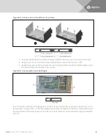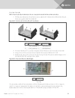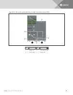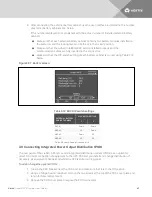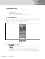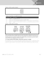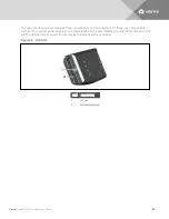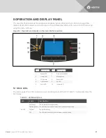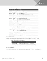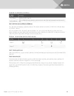
4. Insert the bottom of the POD into the slot provided, and then connect the POD connectors.
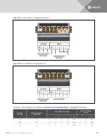
NOTE: The connector should connect only one way, matching the color of the pins.
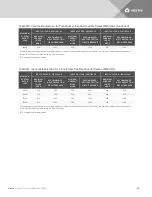
NOTE: Distribution PODs PD2-101, PD2-102, PD2-103, PD2-104, PD2-105, PD2-106 and PD2-107 should
not be used if the UPS output voltage is set to 220/127 V.
NOTE: When connecting distribution POD’s to an AS3 or AS4 frame, the L-L output receptacles
connect to the 240-V taps of the output transformer, not to the 208-V tap. Verify receptacle voltage
and load ratings before energizing the load.
5. Secure the POD by using the two screws removed in step 2.
6. Repeat steps 1 through 5 to install a second POD on the UPS, only the 16-bay frame has two
POD ports.
7. Connect the equipment to the appropriate outlets.
8. Close the POD breaker(s) to connect AC power to the outlets.
9. After commissioning the UPS, power-on the connected equipment per the manufacturer’s
instructions. See
Commissioning/Startup Procedures
3.10 Commissioning/Startup Procedures
The Liebert APS can be commissioned with or without AC power being connected.
3.10.1 Checks before Commissioning/Start-up
1. Verify that the AC-power connections are wired properly and that all connections are tight.
2. If using external battery cabinets or 3-party battery systems, verify that the DC-power and
communication cables are connected properly and that all connections are tight.
3. Measure and record the AC-input voltage and frequency. These are required to properly
configure the output voltage of the Liebert APS system.
4. If any modules were removed from the Liebert APS during installation, verify that all modules
are fully-inserted and that the module locking levers are in the locked position.
5. For Remote Emergency Power Off (REPO) circuit:
•
If connecting the UPS to a REPO circuit, see
REPO (Remote Emergency Power Off)
page 53 for the connection details and instructions.
•
If a REPO circuit is required or used, the factory-installed jumper must be removed from
the terminal-block Pins 9-10 as described in
6. Verify that the internal bypass breaker in the UPS is in the open position with the guard in
place and secure.
3.10.2 Commissioning/Start-up with AC Power Available (Normal-mode Operation)
1. Verify that the up-stream mains AC breaker is closed.
2. Locate the UPS Enable switch on the rear of the unit protected by a clear plastic cover, and
turn it On.
3. Locate the UPS input breaker on the front of transformer-free frame systems and on the rear of
transformer-based frame systems, and turn it off.
The initial system checks begin and power begins charging the battery.
4. Press the ON/OFF button on the LCD panel.
5. When asked to confirm, press Enter (F5 button) to turn On the UPS.
Vertiv
| Liebert® APS™ Installer/User Guide |
48
Summary of Contents for Liebert APS series
Page 1: ...Liebert APS 5 20 kVA Modular UPS Installer User Guide...
Page 6: ...Vertiv Liebert APS Installer User Guide 6...
Page 10: ...Vertiv Liebert APS Installer User Guide 10 This page intentionally left blank...
Page 50: ...Vertiv Liebert APS Installer User Guide 50 This page intentionally left blank...
Page 76: ...Vertiv Liebert APS Installer User Guide 76 This page intentionally left blank...
Page 80: ...Vertiv Liebert APS Installer User Guide 80 This page intentionally left blank...
Page 109: ......

