4 Chapter 1 Overview
Liebert EXM 80kVA ~ 200kVA UPS User Manual
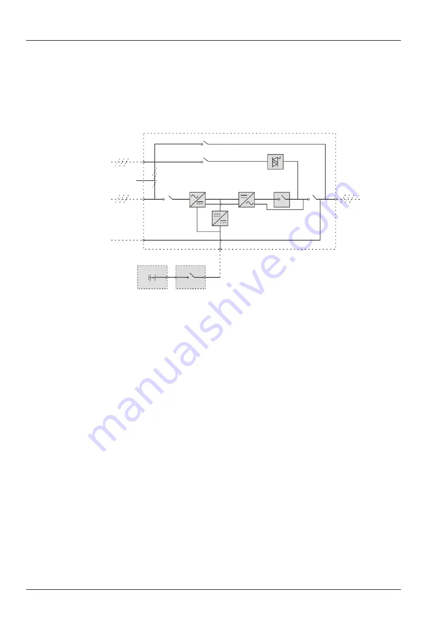
Figure 1-2 describes the block diagram of the UPS module. The UPS has split bypass configuration (that is,
the bypass adopts independent mains input) and common input configuration. If the system adopts
common input configuration, the UPS has shorting copper bar of common input configuration, and the
bypass input switch (Q2) and rectifier input switch (Q1) would be linked together. If the system adopts
split bypass configuartion, just remove the shorting copper bar of common input configuration of the UPS.
During the normal operation of the UPS, except for the maintenance bypass switch Q3, other switches
shall be closed.
Note: Q1, Q2 and Q5 are optional while Q3 is standard.
Bypass input
Static switch
UPS
Output
UPS output
switch Q1
Rectifier
DC bus
Inverter
Inverter
Charger
Battery
BCB
Mains input
of common input
Shorting copper bar
Neutral line input
Maintenance bypass switch Q3
Bypass input switch Q2
Rectifier input
switch switch Q5
configuration
Figure 1-2
UPS power supply switch configuration
Note: The mains input and bypass input share the same neutral line.
1.2.5
Battery Circuit Breaker (BCB)
The external battery shall be connected to the UPS through the BCB. The BCB box is an option, which
shall be installed near the battery. The BCB is closed manually. The BCB has a shunt tripping coil. When
the system is faulty and the BCB needs to be disconnected, the UPS control circuit will send a signal to
the shunt tripping coil so as to trip the BCB. It also has a magnetic trip facility for overload protection and
short circuit protection.
1.3
Parallel System
Up to four UPS modules can be parallel-connected to form a parallel system to increase the system
capacity and reliability. The load is equally shared between the paralleled UPS modules.
Moreover, two UPS modules or parallel system can comprise a dual bus system. Each parallel system has
independent output. Output synchronization is achieved through the LBS cable or LBS device, thus
enabling seamless load transfer between the two parallel systems or single modules through the STS
device.
1.3.1
Parallel System Features
1. The hardware and software of parallel system are completely the same as those of the single module.
The parallel system configuration is achieved through settings in configuration software.
2. Parallel cables are connected in a ring, providing both system reliability and redundancy.
Summary of Contents for EXM 0080kTK16FN01000
Page 2: ......
Page 14: ......
Page 132: ...118 Chapter 8 Options Liebert EXM 80kVA 200kVA UPS User Manual...


