background image


FT-950 

Operating Manual 

Vertex Standard Co., Ltd. 

20 

Pressing this button to reset the status of the functions which is selected from the five 
buttons at the left of this button to factory default. 
 
26. [SELECT] Knob 
This knob is used to adjust the status of the functions depending on the five buttons 
located above this knob. 

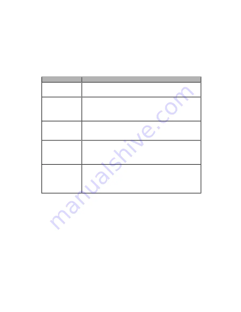
FUNCTION Switch  EFFECT 
SHIFT 

Rotate this knob to vary the passband of the IF DSP filter by 20 
Hz steps. The total adjustment range is ±1 kHz. 
The position of the passband can be observed on the display. 

WIDTH 

Rotate this knob to set the overall bandwidth of the DSP IF 
filter. 
Counter-clockwise rotation reduces the bandwidth, while 
clockwise rotation increases the bandwidth. 
The current bandwidth can be observed on the display. 

CONT 

Pressing this knob to turn the CONTOUR filter on and off. 
Rotate this knob to select the CONTOUR filter response. 
The peak position of the CONTOUR filter can be observed on 
the display. 

NOTCH 

Pressing this knob to turn the IF NOTCH filter on and off. 
Rotate this knob to adjust the center frequency of the IF 
NOTCH filter. 
The null position of the IF NOTCH filter can be observed on the 
display. 

µ-TUNE 

Pressing this knob to turn the optional RF µTuning Kit on and 
off. 
Rotate this knob to adjust the center frequency of the µ-Tuning 
filter. 
The peak position of the µ-Tuning filter can be observed on the 
Tuning Offset Indicator field of the display. 

This knob also uses to select the Menu item when the Menu mode is engaged. 
Press and hold this knob for two seconds to activate the optional Voice Memory feature 
for the SSB/AM/FM modes, or the Contest Keyer for the CW mode. See page ?? (Voice 
Memory feature) or page ?? (Contest Keyer) for details. 
 
27. [(VFO-A) RX] Indicator/Switch 
This button, when pressed, the transceiver receives the VFO-A frequency. The LED 
inside this button will glow green when the transceiver receives the VFO-A frequency. 
When the transceiver receives the VFO-A frequency, pressing this button momentarily 
will mute the receiver, and the indicator will blink. Pressing the button once more will 
restore receiver operation, and the indicator will glow green steadily. 
 
28. QMB (Quick Memory Bank) Switches 

Summary of Contents for FT-950

Page 1: ...erformance both on transmit and receive The FT 950 is designed for the most competitive operating situations whether you primarily operate in contest DX or digital mode environments Built on the foundation of the popular FTdx9000 transceiver and carrying the proud tradition of the FT 1000 series the FT 950 provides up to 100 Watts of power output on SSB CW and FM 25 Watts AM carrier Digital Signal...

Page 2: ... Change Speech Processor IF Monitor for Voice modes CW Pitch control CW Spot switch Full CW QSK adjustable IF Noise Blanker and all mode Squelch Two TX RX antenna ports are provided on the rear panel Two key jacks are provided one each on the front and rear panels and they may be configured independently for paddle input or connection to a straight key or computer driven keying interface The CW Me...

Page 3: ...nly part of the FT 950 story Vertex Standard stands behind our products with a worldwide network of dealers and service centers We greatly appreciate your investment in the FT 950 and we look forward to helping you get the most out of your new transceiver Please feel free to contact your nearest dealer or one of Vertex Standard s national headquarters offices for technical advice interfacing assis...

Page 4: ...trols Switches 16 Display Indications 28 Rear Panel 32 Basic Operation Receiving on Amateur Bands 35 Operation on 60 Meter 5 MHz Band U S version only 38 CLAR Clarifier Operation on Main VFO A 39 LOCK 40 DIM 40 Convenience Features 42 Dual Receive 42 Using Headphones for Dual Receive 43 Sideband Diversity Reception 43 Bandwidth Diversity Reception 44 Polarity Diversity 44 P BACK Audio Playback fro...

Page 5: ...Filter Operation SSB CW RTTY PKT AM Modes 58 Digital Noise Reduction DNR Operation 59 Digital Notch Filter DNF Operation 59 NARROW NAR One Touch IF Filter Selection 60 IF Noise Blanker NB Operation 61 Tools for Comfortable and Effective Reception 62 AGC Automatic Gain Control 62 SLOPED AGC Operation 63 Mute Feature Main VFO A Band 63 SSB AM Mode Transmission 64 Using the Automatic Antenna Tuner 66...

Page 6: ... Convenience Features 81 CW Spotting Zero Beating 81 Using CW Reverse 82 CW Delay Time Setting 83 CW Pitch Adjustment 83 Contest Memory Keyer 84 Message Memory84 Transmitting in the Beacon Mode 85 TEXT Memory 86 Contest Number Programming 87 Decrementing the Contest Number 87 Contest Memory Keyer Using the optional FH 2 Remote Control Keypad 88 Message Memory88 TEXT Memory 90 FM Mode Operation 92 ...

Page 7: ...cket Operation 105 Packet Setup Including Subcarrier Frequency 105 Basic Setup 105 RTTY Radio Teletype Operation 106 Setting Up for RTTY Operation 106 Basic Setup 106 Miscellaneous AFSK Based Data Modes 107 Menu Mode 108 Using the Menu 108 Menu Mode Reset 108 AGC Group 112 DISPLAY Group 112 DVS Group 113 KEYER SETUP Group 114 GENERAL Group 115 S IF SFT Group 116 MODE AM Group 117 MODE CW Group 117...

Page 8: ... 1 pcs P0091046 3 5 mm 2 contact Plug 1 pcs P0090034 RCA Plug 2 pcs P0091365 Operating Manual 1 pc Warranty Card 1 pc Available Options MD 200A8X Ultra High Fidelity Desk Top Microphone MD 100A8X Desk Top Microphone YH 77STA Lightweight Stereo Headphone SP 2000 External Speaker with Audio Filter VL 1000 VP 1000 Linear Amplifier AC Power Supply DMU 2000 Data Management Unit RF µTuning Kit A For 160...

Page 9: ...per DC connections are made consult with a qualified service technician when in doubt Caution Permanent damage can result improper supply voltage or reverse polarity voltage is applied to the FT 950 The Limited Warranty on this transceiver does not cover damage caused by application of AC voltage reverse polarity DC or DC voltage outside the specified range of 13 8 V 10 When replacing fuses be cer...

Page 10: ...heir factory defaults without affecting the memories you have programmed 1 Press the front panel s POWER switch to turn the transceiver off 2 Press and hold in the MENU button while holding it in press and hold in the front panel s POWER switch to turn the transceiver on Once the transceiver comes on you may release the MENU button Full Reset Use this procedure to restore all Menu Memory settings ...

Page 11: ...Ohm coaxial cable for the lead in to your FT 950 transceiver All efforts at providing an efficient antenna system will be wasted if poor quality lossy coaxial cable is used This transceiver utilizes standard M PL 259 type connectors Grounding The FT 950 transceiver like any other HF communications apparatus requires an effective ground system for maximum electrical safety and best communications e...

Page 12: ...electrical device to another and thence to the ground bus This so called Daisy Chain grounding technique may nullify any attempt at effective radio frequency grounding See the drawing below for examples of proper grounding techniques Inspect the ground system inside the station as well as outside on a regular basis so as to ensure maximum performance and safety Besides following the above guidelin...

Page 13: ...of which will be detailed in the Operation section later Besides the built in Electronic Keyer two key jacks are provided one each on the front and rear panels for convenient connection to keying devices The Menu system allows you to configure the front and rear panel KEY jacks according to the device you wish to connect For example you may connect your keyer paddle to the front panel KEY jack and...

Page 14: ...ng positive amplifier relay coil voltages of up to 60VDC at 200 mA or 30 VDC at 1 A If you plan on using multiple linear amplifiers for different bands you must provide external band switching of the Linear Tx relay control line from the TX GND OUT line at the LINEAR jack Important Note Do not exceed the maximum voltage or current ratings for the TX GND OUT pin pin 2 of the LINEAR jack This line i...

Page 15: ...automatic antenna tuner rematches the antenna system impedance for minimum SWR The resulting setting is automatically stored in one of the antenna tuner s 100 memories for instant automatic recall later when the receiver is tuned near the same frequency Pressing this button momentarily while the Tuner is engaged will take the Automatic Antenna tuner out of the transmit line Note When the Automatic...

Page 16: ...uality 7 PROC Processor Switch This button enables the Parametric Microphone Equalizer and Speech Processor for SSB AM transmission When the Parametric Microphone Equalizer is activated the MIC EQ icon appears in the display When the Speech Processor is activated the MIC EQ and PROC icons appear in the display Adjustment of the Processor level is accomplished via the Menu item 109 TGEN PROCLVL Adv...

Page 17: ... change according to the AGC characteristics selected Press the AGC button repeatedly to select the desired receiver recovery time constant Press and hold in the AGC button for two seconds to disable the AGC for testing or weak signal reception Advice The Attenuator may be used in conjunction with the IPO button to provide two stages of signal reduction when an extremely strong signal is being rec...

Page 18: ...right edge of the ALC scale Then when you speak in a more normal voice level you ll be certain not to be over driving the mic amplifier stage 15 SPEED Knob This knob adjusts the keying speed of the internal CW keyer 4 60 WPM Clockwise rotation increases the sending speed When turning this knob while pressing the KEYER button the frequency display shows the keying speed 16 Microphone Connector This...

Page 19: ... adjust the IF DSP bandwidth using the SELECT knob While activated the LED inside this button glows orange 21 WIDTH Switch Pressing this button allows you to adjust the overall bandwidth of the IF DSP filter using the SELECT knob While activated the LED inside this button glows orange 22 CONT Switch Pressing this button allows you to select the DSP Contour filter response using the SELECT knob Whi...

Page 20: ...NOTCH filter on and off Rotate this knob to adjust the center frequency of the IF NOTCH filter The null position of the IF NOTCH filter can be observed on the display µ TUNE Pressing this knob to turn the optional RF µTuning Kit on and off Rotate this knob to adjust the center frequency of the µ Tuning filter The peak position of the µ Tuning filter can be observed on the Tuning Offset Indicator f...

Page 21: ...ide 5 0 kHz Dev 25 0 kHz BW and narrow 2 5 kHz Dev 12 5 kHz BW 30 SPLIT Switch Pressing this button to activate split frequency operation between the VFO A used for reception and the VFO B used for transmission If you press and hold in the SPLIT button for two seconds the Quick Split feature will be engaged whereby the VFO B will automatically be set to a frequency 5 kHz higher than the VFO A freq...

Page 22: ... kHz AM FM PKT FM 100 Hz 1 kHz 100 kHz 1 MHz Numbers in parentheses indicate steps when the FAST button is ON Advice The tuning steps for the Main Tuning Dial knob are set at the factory to 10 Hz per step Via Menu item 084 TUN DIALSTP however you may change this setting from 10 Hz to 1 Hz instead When 1 Hz basic steps are selected the action of the FAST button will be changed to 1 10 of the values...

Page 23: ...ch Pressing this button momentarily exchanges the contents of the VFO A or a recalled memory channel and the VFO B 44 V M Switch This button toggles frequency control between the memory system and the VFO A Either MR or MT icon will be displayed to the under the frequency display field to indicate the current selection If you have tuned off of a Memory channel frequency MT icon is appeared pressin...

Page 24: ...M 49 ATT Switch This button selects the degree of attenuation if any to be applied to the receiver input Available selections are 6 dB 12 dB 18 dB or OFF and the selected attenuation level appears in the ATT column of the Block Diagram Display on the display Advice The Attenuator may be used in conjunction with the IPO switch to provide two stages of signal reduction when an extremely strong signa...

Page 25: ...F GAIN o RF GAIN Knobs AF GAIN Knob The inner AF GAIN knob sets the receiver s audio volume level Typically you will operate with this control set between the 9 o clock and 10 o clock positions RF GAIN Knob The outer RF GAIN knob is the receiver s RF gain control which adjusts the gain of the receiver s RF and IF amplifier stages This control is normally left in the fully clockwise position 54 RX ...

Page 26: ...de the red LED imbedded within the button will light up Pressing this button again will transfer frequency mode control back to the VFO A side and the red LED imbedded within this button will turn off 59 BAND Switch Pressing this button allows you to select the operating band Amateur bands using the CLAR VFO B knob 60 GRP Switch Pressing this button allows you to select the memory group using the ...

Page 27: ... Speech Processor is activated 2 MONI This indicator appears whenever the transmit monitor circuit is activated 3 KEYER This indicator appears whenever the internal CW keyer is activated 4 BK IN This indicator appears whenever CW break in operation is activated 5 NB This indicator appears when the receiver s short duration Noise Blanker is activated This indicator will blink for three seconds and ...

Page 28: ...nna Tuner is activated 10 HI SWR This indicator appears if the directional coupler and microprocessor detect an abnormally high SWR condition over 3 0 1 that cannot be resolved by the Automatic Antenna Tuner Note If this indicator appears check to be sure that you have the correct antenna selected on the current operating band If so you will need to check the condition of the antenna its coaxial c...

Page 29: ...front end RF amplifier selected for operation by the front panel IPO button R FLT Indicates the IF Roofing Filter selected AUTO mode determined 3 kHz 6 kHz or 15 kHz AGC AUTO FAST MID SLOW Indicates the AGC decay time selected for operation by the front panel AGC switch 15 DNR This indicator appears whenever the Digital Noise Reduction feature is activated 16 DNF This indicator appears whenever th...

Page 30: ...ocked 25 LSB USB CW AM FM RTTY PKT Displays the currently selected operating mode 26 Frequency Display This is the frequency display Advice When setting the Menu items the Menu item number Menu group name and Menu item name will appear in this area during setup When setting the CTCSS frequency for Encoding or Tone Squelch operation the current tone information will appear in this area during setup...

Page 31: ...d by while a Positive frequency shift will be indicated by When setting the Menu items the current setting will appear in this area When setting the CTCSS frequency for Encoding or Tone Squelch operation the current repeater shift direction will appear in this area When controlling the optional rotator the antenna direction will appear in this area during setup Rear Panel 1 ANT 1 2 Jacks Connect y...

Page 32: ...es band selection data which may be used for control of optional accessories such as the VL 1000 Solid state Linear Amplifier Pinout is shown on page 7 TUNER Jack This 8 pin output jack is used for connection to the FC 40 External Automatic Antenna Tuner Pinout is shown on page 8 RTTY PKT Jack This 6 pin input output jack accepts AFSK input from a Terminal Node Controller TNC it also provides fixe...

Page 33: ...t jack accepts a CW key or keyer paddle A 2 contact plug cannot be used in this jack Key up voltage is 5 V and key down current is 1 mA Plug wiring is shown on page and this jack may be configured for keyer Bug straight key or computer keying interface operation via Menu item 039 A1A R TYPE 14 µ TUNE Jack This 10 pin mini DIN jack used for control of the optional RF µTuning Kit 15 DMU Jack This 8 ...

Page 34: ...ing Kit is connected the transceiver is ready for full operation 3 The transceiver will start up on 7 000 00 MHz LSB and normal operation may begin Note To turn power off press and hold in the front panel POWER switch for two seconds 4 Rotate the AF GAIN knob to set a comfortable audio level on incoming signals or noise Clockwise rotation of the AF GAIN knob increases the volume level Note When us...

Page 35: ...dvice Once you have made your antenna selection that antenna is remembered by the microprocessor in conjunction with the VFO register in use when you chose that particular antenna 8 Press the appropriate MODE button to select the desired operating mode Pressing the SSB button toggles the LSB and USB mode and also pressing the SSB button toggles the AM and FM mode Advice By convention in the Amateu...

Page 36: ...ate quickly so as to effect rapid frequency change there are several techniques available Direct keyboard entry of the frequency see page Use the CLAR VFO B knob to tune in 1 MHz steps see page Use the microphone s UP DWN scanning keys if your microphone is so equipped see page Operation on 60 Meter 5 MHz Band U S version only The FT 950 includes the capability for transmission and reception on th...

Page 37: ...ivate it via the Clarifier s RX CLAR and TX CLAR buttons This feature is ideal for following a drifting station or for setting small frequency offsets sometimes utilized in DX Split work Here is the technique for utilizing the Clarifier 1 Press the RX CLAR button In the Multi Display Window the RX notation will appear and the programmed offset will be applied to the receive frequency 2 Rotation of...

Page 38: ...ng and exit to normal operation LOCK You may lock the setting of the Main Tuning Dial knob for VFO A frequency tuning and the CLA VFO B knob for VFO B frequency tuning to prevent accidental To lock out the Main Tuning Dial knob and the CLA VFO B knob just press the LOCK button that is located to the right of the Main Tuning Dial knob To unlock the Dial setting and restore normal tuning just press ...

Page 39: ...which is described later can also be used on VFO B About the only things you can not do with the VFO B that you can with the VFO A are store the contents directly into a memory and set the Clarifier For these functions you need to swap the VFO B with the VFO A by pressing the A B button then store the contents into the memory or set the Clarifier MY Bands Operation When operating on an Amateur Ban...

Page 40: ...ll glow orange 2 Rotate the CLAR VFO B knob to choose the Amateur band on which you wish to operate Only those Amateur bands that have not been skipped will appear as you scroll through the bands To disable the My Band Operation press the BAND button again the imbedded orange LED goes out Advice The My Band feature affects both the VFO A and VFO B Band Stack Operation The FT 950 utilizes a triple ...

Page 41: ... the C S button The programmed Menu item will appear on the display You may now rotate the CLAR VFO B knob to change the setting of this menu item Press and hold the MENU button for two seconds when you are done to save the new configuration and exit to normal operation Rotator Control Functions When using a YAESU model G 800DXA G 1000DXA or G 2800DXA rotator not supplied it is possible to control...

Page 42: ...equency entry process Now beginning with the 10 MHz digit of the frequency the leftmost digit we will enter the required digits of the frequency 2 Press in order the digits of the operating frequency using the BAND buttons which have the frequency entry digit or decimal point on the right side of the slash bar In this example enter 1 8 1 10 4 GEN 3 5 2 14 5 50 0 50 0 50 0 50 0 The decimal point af...

Page 43: ...88 TUN FM STEP Receiver Operation Front End Block Diagram The FT 950 includes a wide range of special features to suppress the many types of interference that may be encountered on the HF bands However real world interference conditions are constantly changing so optimum setting of the controls is somewhat of an art requiring familiarity with the types of interference and the subtle effects of som...

Page 44: ...cantly reduce if not eliminate an interfering carrier DNF Digital Notch filter See page When multiple interfering carriers are encountered during reception the Digital Notch Filter can significantly reduce the level of these signals DNR Digital Noise Reduction See page The DSP s Digital Noise Reduction DNR feature utilizes sixteen different mathematical algorithms to analyze and suppress different...

Page 45: ...between sensitivity noise and interference immunity Also once you have tuned in a station you want to work you may want to reduce sensitivity further or add more attenuation by pressing the ATT button to a more setting This reduces the strength of all signals and noise and can make reception more comfortable important especially during long QSOs When looking for weak signals on a quiet band you wi...

Page 46: ...ference Advice The amount of change in the center frequency of the µ Tune filter when rotating the SELECT knob by one click can be configured using Menu item 032 GENE µT DIAL If you have performed manual adjustment of the µ Tune filter center frequency you may press the CLEAR button to re center the filter response on your current operating frequency 4 Press the SELECT knob momentarily once more t...

Page 47: ...ick Note The permeability tuning concept utilized in the µ Tune circuit dates back many decades as it was incorporated in such classic transceivers as the FT 101 and FT 901 series in addition to the FT DX 400 and similar models The µ Tuning Kit uses a same circuit of our flag ship model FTDX9000 which is the highest development of this circuit concept ever employed in an Amateur transceiver IPO In...

Page 48: ...phone band you may wish to select for example the 3 kHz roofing filter for SSB operation Press the R FLT button to toggle the Roofing Filter selection AUTO 15 kHz 6 kHz 3 kHz AUTO Advice As you repeatedly press the R FLT button you will observe changes in the notation in the R FLT column of the Block Diagram Display on the display denoting the Roofing Filter currently in use Typically this selecti...

Page 49: ...uration man made pulse noise The NB icon will blink for five seconds and thereafter will appear continuously to confirm that the Wide NB is operating 2 Adjust the Noise Blanker level via the Menu item 067 RGEN NB LVL to the point where the offending noise is best reduced or eliminated if desired See box below for details 3 To end Noise Blanker operation press the NB button once more The NB icon wi...

Page 50: ...l sounding audio reproduction on the incoming signal 4 Press the CLEAR button to move the null or peak position to center 5 To cancel Contour tuning press the SELECT button once more The graphic disappears from the CONTOUR indicator on the display confirming that the Contour filter is no longer operation Advice The Contour filter selection will be memorized independently on each VFO stack of the V...

Page 51: ...roving copy the incoming signal itself may have undesirable or excessive frequency components especially in the low frequency range around 100 400 Hz By judicious use of the Contour filter the shoulder of the passband response may be altered or components removed from within the passband allowing the desired signal to rise above the background noise and interference in a manner not obtainable with...

Page 52: ...l fidelity when interference on the band is low 1 Press the WIDTH button The LED inside the WIDTH button glows orange The SELECT knob works as the WITDH knob The current bandwidth appears in the WIDTH indicator on the display 2 Rotate the SELECT knob to the left or right to reduce the interference 3 Press the CLEAR button to set the bandwidth to default Advice The IF Bandwidth will be memorized in...

Page 53: ...ay also yield additional signal enhancement benefits on the net residual bandwidth What s more the IF NOTCH Filter described later may also be utilized in conjunction with the three other filter systems to significant advantage NARROW NAR One Touch IF Filter Selection Pressing the NAR button provides one touch mode specific selection of a narrow IF DSP filter setting that does not depend on the se...

Page 54: ...s the CLEAR button to move the null position to center 5 To cancel the NOTCH filter press the SELECT button once more The graphic disappears from the NOTCH indicator on the display confirming that the NOTCH filter is no longer operation Advice The IF NOTCH Filter selection will be memorized independently on each VFO stack of the VFO A and VFO B The width of the IF NOTCH null may be adjusted using ...

Page 55: ... new setting and exit to normal operation To disable the Digital NOTCH Filter just repeat the above procedure rotating the CLAR VFO B knob to select OFF in step 3 above The DNF icon will turn off confirming that the Digital NOTCH Filter is not active Advice The Digital NOTCH Filter selection will be memorized independently on each VFO stack of the VFO A and VFO B Digital Noise Reduction DNR Operat...

Page 56: ...the point of maximum sensitivity 2 Counter clockwise rotation of the RF GAIN knob will gradually reduce the system gain Advice As the RF GAIN knob is rotated counterclockwise to reduce the gain the S meter reading will rise This indicates that the AGC voltage being applied to the receiver is increasing which causes a reduction in receiver gain Rotating the RF GAIN knob control to the fully counter...

Page 57: ...utton for two seconds to save the new setting and exit to normal operation AGC Automatic Gain Control The AGC system is designed to help compensate for fading and other propagation effects with characteristics that can be of particular value on each operating mode The basic objective of AGC is to maintain a constant audio output level once a certain minimum threshold of signal strength is achieved...

Page 58: ...mance of the FT 950 Terminology Automatic Gain Control or AGC is a circuit that senses the incoming signal strength and then limits the gains of the RF and IF stages so as to keep the output audio volume at a more or less constant level AGC also protects the RF IF Audio and DSP stages from overload as it limits the signal strength that is allowed to flow irrespective of the input signal level Mute...

Page 59: ...rnatively you may use the UP DWN scanning buttons on the MH 31B8 Hand Microphone to sweep up or down the current band 4 Press the microphone s PTT Push To Talk switch to begin transmission speak into the microphone in a normal voice level Advice The TX indicator will light up in the frequency display area confirming that transmission is in progress When transmitting in the AM mode set a maximum ca...

Page 60: ...y be using the frequency Four techniques for exercising Transmit Receive control are provided on the FT 950 and you may choose the technique s that best suit your operating needs Pressing the microphone s PTT switch will engage the transmitter The rear panel PTT jack may be connected to a foot switch or other manual switching device in order to engage the transmitter Pressing the front panel MOX b...

Page 61: ...the need to retune the ATU The ATU in the FT 950 is designed to match impedances within the range of 16 5 Ohms to 150 Ohms corresponding to an SWR of 3 1 or less on the HF amateur bands 6 m band 25 Ohms to 100 Ohms corresponding to an SWR of 2 1 or less Accordingly simple non resonant whip antennas along with random length wires and the G5RV antenna on most bands may not be within the impedance ma...

Page 62: ... rear panel antenna jack reception is not affected by the ATU Quick Points As shipped from the factory only one ATU alignment point is saved on each Amateur band This was memorized during the final alignment and performance verification stages on the production line The momentary flickering of the TUNER icon occurs whenever you cross over into a new 10 kHz ATU memory window Note Please check the o...

Page 63: ...be repeated SWR Post tuning Greater than 3 1 The HI SWR LED will light up and tuning settings if achieved will not be memorized Please investigate and resolve the high SWR condition before attempting further operation using this antenna Enhancing Transmit Signal Quality Adjusting the SSB Transmitted Bandwidth SSB Mode For transmission on SSB a default bandwidth of 2 4 kHz is provided This bandwidt...

Page 64: ...ndwidth will be particularly enjoyable on the low bands during local rag chew QSOs The 3000WB setting is a special hi fidelity setting whereby the transmitted bandwidth is in excess of 3 kHz This selection in conjunction with judicious adjustment of the Parametric Microphone Equalizer see next chapter can provide truly outstanding fidelity and very natural sounding audio When using the wider bandw...

Page 65: ...ommend you consider connecting a dummy load to one of the Antenna jacks and monitor your signal on a separate receiver so as to prevent interference to other users You will have the best chance of hearing the effects of adjustments if you wear headphones connected to the monitor receiver while monitoring your transmitted signal 3 To adjust the Parametric Microphone Equalizer while the speech proce...

Page 66: ... a 10 dB null at 100 Hz with a bandwidth of 1 or 2 do about a 3 dB null centered on 800 Hz with a bandwidth of 3 and then put an 8 dB peak centered on 2100 Hz with a bandwidth of 1 These are starting recommendations each microphone and user s voice will be different often requiring different settings Activating the Parametric Microphone Equalizer 1 Adjust the MIC GAIN knob for SSB use as described...

Page 67: ...1 10 Using the Speech Processor SSB and AM Modes The FT 950 s Speech Processor is designed to increase talk power by increasing the average power output via a sophisticated compression technique and adjusting the audio quality to the menu settings 100 TAUD PE1 FRQ 103 TAUD PE2 FRQ 106 TAUD PE3 FRQ The result is improved intelligibility when conditions are difficult 1 Adjust the MIC GAIN knob for S...

Page 68: ...und quality as you make adjustments You may set the RF power output via the Menu item 111 TGEN TX PWR whether or not the Speech Processor is engaged You may adjust the Parametric Microphone Equalizer when the speech processor is engaged using Menu Items 100 through 108 See page for details When the optional DMU 2000 Data Management Unit is connected you may observe the effect of your compression l...

Page 69: ...REC icon will glow steadily and recording will begin If you do not press the PTT switch within five seconds of pressing the SELECT knob the memory storage process will be cancelled 6 Speak into the microphone in a normal voice level to record the message such as CQ DX CQ DX this is W 6 Delta X Ray Charlie W 6 Delta X Ray Charlie Over Remember that the time limit for recording any message is 20 sec...

Page 70: ...pad You may also utilize the Voice Memory capability of the FT 950 from the optional FH 2 Remote Control Keypad which plugs into the rear panel s REM jack Recording Your Own Voice in Memory 1 Select the LSB USB AM or FM mode using the front panel MODE buttons 2 Press the MEM key on the FH 2 A blinking REC icon will appear in the display 3 Press any of the FH 2 s keys numbered 1 through 5 to select...

Page 71: ...ce Operated TX RX Control system provides hands free automatic activation of the transmitter based on voice input into the microphone 1 Press the VOX button to activate the VOX circuitry The LED inside the VOX button glows red 2 Without pressing the PTT switch speak into the microphone in a normal voice level When you start speaking the transmitter should be activated automatically When you finish...

Page 72: ...ief syllable like Ah and listening to the hang time so as to set the desired delay When your adjustments are complete press and hold in the MENU button for two seconds to save the new setting and exit to normal operation The Anti Trip setting sets the negative feedback of receiver audio to the microphone to prevent receiver audio from activating the transmitter via the microphone can also be adjus...

Page 73: ...ntly used for receiver offset tuning However for DX pile ups where the DX station is using a split of less than 10 kHz the TX Clarifier function is usually the quickest way to set the transmitter to the desired offset frequency 2 Rotate the CLAR VFO B knob to set the desired transmitter offset A maximum split of 9 99 kHz may be set 3 To exit from TX Clarifier operation press the TX CLAR button onc...

Page 74: ... the Menu item display between 006 DISP and BAR SEL 3 Rotate the SELECT knob to select CLAr from the available choices the factory default is C tn 4 Press and hold in the MENU button for two seconds to save the new setting and exit to normal operation Split Frequency Operation A powerful capability of the FT 950 is its flexibility in Split Frequency operation using the VFO A and VFO B frequency re...

Page 75: ...mporarily while pressing the TXW button located on the bottom left of the Main Tuning Dial knob It is possible to set different operating modes for example LSB and USB on the two VFOs used during Split operation During Split operation it also is possible to set the VFO A and VFO B to different Amateur bands if you used the multi band antenna Quick Split Operation The Quick Split feature allows you...

Page 76: ...fault 5 kHz 4 Press and hold in the MENU button for two seconds to save the new setting and exit to normal operation CW Mode Operation The powerful CW operating capabilities of the FT 950 include operation using both an electronic keyer paddle and a straight key or emulation thereof as is provided by a computer based keying device Setup for Straight Key and Straight Key emulation Operation Before ...

Page 77: ...l during contest and traffic handling operations 4 Operation using your CW key may now proceed Advice You may adjust the CW sidetone level by the MONI knob Rotate the MONI knob for a comfortable listening level on the CW sidetone To disable the CW monitor press the MONI button the MONI icon is disappeared If you set the BK IN button to Off you may practice your sending without having the signal go...

Page 78: ...l appear in the display confirming that the built in Electronic Keyer is now active 4 Rotate the SPEED knob to set the desired sending speed 4 60 WPM Clockwise rotation of the SPEED knob will increase the keying speed Advice You may confirm the keying speed when turning the SPEED knob while pressing the KEYER button The frequency display shows the keying speed temporarily When you press either the...

Page 79: ...the Menu 2 Rotate the SELECT knob so as to select Menu item 043 A1A BK IN Advice Press the SELECT knob to toggle the Menu item display between 043 A1A and BK IN 3 Rotate the CLAR VFO B knob to set this Menu item to FuLL 4 When your adjustments are complete press and hold in the MENU button for two seconds to save the new setting and exit to normal operation A number of interesting and useful featu...

Page 80: ...f straight key mode buG Dots will be generated automatically by the keyer but dashes must be sent manually ELE Both dots and dashes will be generated automatically when you use your paddle ACS Same as ELEKEY except that the spacing between characters is precisely set by the keyer to be the same length as a dash three dots in length 4 When you are finished press and hold in the MENU button for two ...

Page 81: ...set Indicator is already set to the C tn selection Quick Points The CW Spotting process utilizes the Spot tone or the Tuning Offset Indicator The actual offset pitches being set by the Menu item 045 A1A PITCH see page The offset pitch may be set to any frequency between 300 Hz and 1050 Hz in 50 Hz steps and you can either match tones audibly using the SPOT button or align the receiver frequency so...

Page 82: ...ration Figure A demonstrates the normal CW injection setup using the USB side In Figure B CW Reverse has been engaged so as to receive using LSB side injection to eliminate interference The beneficial effect of switching sidebands can clearly be seen in this example Notes When CW Reverse is engaged the Tuning Offset Indicator action will concurrently be reversed as to its indication When the incom...

Page 83: ... display between 045 A1A and PITCH 3 Rotate the CLAR VFO B knob to select the desired tone 4 When you are finished press and hold in the MENU button for two seconds to save the new setting and exit to normal operation Advice You may confirm the Spot tone frequency when pressing the SPOT button The frequency display will shows the Spot tone frequency Terminology CW Pitch If you tuned to an exact ze...

Page 84: ...ou wish to store the message for now we are just selecting the message entry technique Keyer entry 019 KEY CW MEM1 020 KEY CW MEM2 021 KEY CW MEM3 022 KEY CW MEM4 023 KEY CW MEM5 Advice Press the SELECT knob to toggle the Menu item display between Menu Item Number Group Name and Menu Function 3 Rotate the CLAR VFO B knob to set the selected CW Memory Register to tyP2 If you want to use your keyer ...

Page 85: ...red message For ease in setting up the keyer memories we recommend you set Menu item 037 A1A F TYPE and or 039 A1A R TYPE to ACS Automatic Character Spacing while you are programming the keyer memories Checking the CW Memory Contents 1 Be sure that Break in is still turned Off by the BK IN button 2 Press the MONI button to enable the CW monitor A MONI icon will appear in the display 3 Press and ho...

Page 86: ...via the Text input method The time delay between message repeats may be set anywhere between 1 and 255 seconds via Menu item 016 KEY BEACON If you do not wish the message to repeat in a Beacon mode please set this Menu item to OFF To transmit the message 1 Press and hold the SELECT knob for two seconds to activate the Contest Memory Keyer Indicates one of following indication in Multi Display Wind...

Page 87: ... MENU button for two seconds to save the new settings and exit Text Message Programming 1 Press the CW button to set the operating mode to CW 2 Be sure that the Break in is Off by pressing the BK IN button if necessary 3 Press and hold the SELECT knob for two seconds to activate the Contest Memory Keyer Indicates one of following indication in Multi Display Window on the display rEC1 rEC2 rEC3 rEC...

Page 88: ...splay REC1 REC2 REC3 REC4 REC5 PLY1 PLY2 PLY3 PLY4 and PLY5 4 Rotate the SELECT knob to select the CW Memory Register PLY1 through PLY5 whichever one you just recorded in 5 Press the SELECT knob A PLAY icon will appear in the display and you will hear the results in the sidetone but no RF energy will be transmitted Note Adjust the monitor level using the MONI knob On The Air CW Message Playback 1 ...

Page 89: ...lay between 018 KEY and CONTEST 3 Rotate the CLAR VFO B knob to set the Contest Number to the desired value Advice Press the CLEAR button located at the upper right of the SELECT knob to reset the Contest Number to 1 4 Press and hold the MENU button for two seconds more to store the new number and exit Contest Memory Keyer Using the optional FH 2 Remote Control Keypad You may also utilize the CW m...

Page 90: ...of the FH 2 s keys numbered 1 through 5 to begin the memory storage process and the REC icon will glow steadily 6 Send the desired message using your keyer paddle Advice If you do not keying within ten seconds the memory storage process will be cancelled 7 Press the MEM key on the FH 2 once more at the end of your message Up to 50 characters may be stored among the five memories Note you must exer...

Page 91: ...yer paddle input will not be transferred over when you select Text Memory technique on a particular memory register the Menu Mode Setting is set to tyP1 TEXT Memory The five channels of CW message memory up to 50 characters total may also be programmed using a text entry technique This technique is somewhat slower than when you send the message directly from your keyer paddle but accuracy of chara...

Page 92: ...mber to be programmed in each slot of the memory In the case of the second example above the character designates the slot where the Contest Number will appear Advice You may also use the Main Tuning Dial knob and the CLAR VFO B knobs to program the message characters 6 When the message is complete add the character at the end to signify the termination of the message 7 Press and hold in the FH 2 ...

Page 93: ...ementing the Contest Number Use this process if the current contest number gets slightly ahead of the actual number you want to send in case of a duplicate QSO for example Press the FH 2 s DEC key momentarily The current Contest Number will be reduced by one Press the FH 2 s DEC key as many times as necessary to reach the desired number If you go too far use the Contest Number Programming techniqu...

Page 94: ...f CTCSS Tone operation is desired needed press and hold in the AM FM button for two seconds to engage the CTCSS mode 3 Rotate the Main Tuning Dial knob to select the desired CTCSS mode If you just need to send the uplink encoding tone select TN For encode decode operation choose TS instead The available choices are OFF TN Tone Encoder TS Tone Squelch OFF 4 Rotate the CLAR VFO B knob to select the ...

Page 95: ...in Tuning Dial to choose TS from the available choices of OFF TN Tone Encoder TS Tone Squelch OFF 4 Rotate the CLAR VFO B knob to select the desired CTCSS Tone to be used A total of 50 standard CTCSS tones are provided see the CTCSS Tone Chart 5 Press and hold in the AM FM button for two seconds A D notation will indicate on the 10 Hz frequency digit in the display that the Tone Decoder is engaged...

Page 96: ...us Repeater Shift Direction and Shift Frequency CTCSS status and Tone Frequency QMB Quick Memory Bank The Quick Memory Bank consists of five memories labeled C 1 through C 5 independent from the regular and PMS memories These can quickly store operating parameters for later recall QMB Channel Storage 1 Tune to the desired frequency on the VFO A 2 Press the blue QMB STO button The beep will confirm...

Page 97: ...o 99 memories each storing frequency mode and a wide variety of status information detailed previously Memories may be grouped into as many as six Memory Groups and additionally you get nine pairs of band limit PMS memories along with five QMB Quick Memory Bank memories Memory Storage 1 Set the VFO A up with all frequency mode and status the way you want to have it stored 2 Press the A M button mo...

Page 98: ...tus Before programming a channel into memory you can check the current contents of that channel without the danger of over writing the channel accidentally 1 Press the A M button momentarily The data stored in the currently selected memory channel will be displayed in the frequency field However since you are only checking the contents of the memory channel your radio will not have moved to the me...

Page 99: ... go to the Memory mode The memory channel number will appear in the multi panel window Advice If you can not enter the Memory mode check to be sure that the VFO B RX Indicator Switch is illuminated green If it is press the VFO A RX Indicator Switch to make the VFO B RX Indicator Switch go out then press the V M button again 2 Press the MCH button The orange LED inside the switch will light up indi...

Page 100: ...Note Computer software programs utilizing the CAT system interface port may presume that the transceiver is operating in the VFO mode for certain features like band mapping and or frequency logging Because the Memory Tune mode so closely resembles the VFO mode be sure that you have the FT 950 operating in a control mode compatible with your software s requirements Use the VFO mode if you re not su...

Page 101: ... Desired Memory Group You may recall memories just within a particular Memory Group if desired 1 Press the V M button if necessary to enter the Memory mode Advice If you can not enter the Memory mode check to be sure that the VFO B RX Indicator Switch is illuminated green If it is press the VFO A RX Indicator Switch to make the VFO B RX Indicator Switch go out then press the V M button again 2 Pre...

Page 102: ... normal operation Emergency communication on this spot frequency is now possible 5 Press the V M button as necessary to enter the Memory mode Press the MCH button then rotate the CLAR VFO B knob to select the emergency channel EUS which is found between channels US5 and 01 Note The receive mode CLARIFIER functions normally while using this frequency but variation of the transmit frequency is not p...

Page 103: ... five seconds On the SSB CW and SSB based Data modes the scanner will pause on a received signal then will step across the signal very slowly giving you time to stop the scan if you like In these modes on the VFO the scanner does not stop however 5 To cancel the scanning press the microphone s UP or DWN key momentarily Advice You may select the manner in which the scanner resumes while it has paus...

Page 104: ...n a signal using Menu item 034 GEnE SCN RSM During memory scanning the default 5Sec setting will cause the scanner to resume scanning after five seconds you may change it however to resume only after the carrier has dropped out if you like See page Quick Point If you have no interest in scanning and wish to prohibit the microphone s UP DOWN keys from initiating scanning you may disable scanning co...

Page 105: ...the decimal point between the MHz and kHz digits of the frequency display will blink If the incoming signal disappears scanning will resume in about five seconds On the SSB CW and SSB based Data modes the scanner will pause on a received signal then will step across the signal very slowly giving you time to stop the scan if you like In these modes on the VFO the scanner does not stop however If th...

Page 106: ... you need to do FM based 1200 baud packet on the 29 50 MHz bands press the RTTY PKT button repeatedly until the PKT and FM icons will appear on the display to engage the PKT FM mode When both the PKT and USB icons are appeared on the display the FT 950 has engaged Packet operation in the USB mode 2 When the transmit command is received from the TNC the transmitter of the FT 950 will automatically ...

Page 107: ...illustration for details regarding connection to your TU Setting Up for RTTY Operation Before commencing RTTY operation please direct your attention to the setup steps shown in the chart to the right Menu Item Available Values 059 RTTY R PLRTY Nor normal rEU reverse 060 RTTY T PLRTY Nor normal rEU reverse 061 RTTY OUT LEL 0 100 062 RTTY SHIFT 170 200 425 850 Hz 063 RTTY TONE 1275 2125 Hz Basic Set...

Page 108: ...ient signal strength If this is observed there may be a Mark Space polarity problem between your station and the other station If so try setting Menu item 059 RTTY R PLRTY to rEU Reverse to see if that permits copy A separate Menu Item permits reversal of your transmitter s Mark Space polarity 060 RTTY T PLRTY Quick Point In the FT 950 RTTY is a mode defined as being an FSK mode whereby the closin...

Page 109: ...ou wish to work on 3 Rotate the CLAR VFO B knob to change the current setting of the selected Menu item 4 When you have finished making your adjustments press and hold in the MENU button for two seconds to save the new setting and exit to normal operation If you only momentarily press the MENU button the new settings will not be retained Menu Mode Reset You may reset all the Menu settings to their...

Page 110: ...COOL BLUE Advice If the optional DMU 2000 Data Management Unit is not connected this adjustment has no effect 005 DISP DIM VFD Function Setting of the display brightness level Available Values 0 7 Default Setting 4 006 DISP BAR SEL Function Selects one of three parameters to be viewed on the Tuning Offset Indicator Available Values CLAr C tn u tn Default Setting C tn CLAr Displays relative clarifi...

Page 111: ...ting OFF 011 DISP RTR STU Function Selects the starting point of your rotator controller s indicator needle Available Values 0 90 180 270 Default Setting 0 Advice If the optional DMU 2000 Data Management Unit is not connected this adjustment has no effect 012 DISP RTR ADJ Function Adjusts the indicator needle precisely to the starting point set in menu item 011 DISP RTR STU Available Values 30 0 D...

Page 112: ...ne input level to the optional Voice Memory Unit Available Values 0 100 Default 50 Advice If the optional Voice Memory Unit is not connected this adjustment has no effect KEYER SETUP Group 016 KEY BEACON Function Sets the interval time between repeats of the beacon message Available Values OFF 1 255 sec Default Setting OFF 017 KEY NUM STL Function Selects the Contest Number Cut format for an imbed...

Page 113: ...e for message register 1 Available Values tyP1 tyP2 Default Setting tyP2 tyP1 You may enter the CW message from the Main Tuning Dial knob and CLAR VFO B knob tyP2 You may enter the CW message from the CW keyer 020 KEY CW MEM2 Function Permits entry of the CW message for message register 2 Available Values tyP1 tyP2 Default Setting tyP2 tyP1 You may enter the CW message from the Main Tuning Dial kn...

Page 114: ... Tuning Dial knob and CLAR VFO B knob tyP2 You may enter the CW message from the CW keyer GENERAL Group 024 GENE ANT SEL Function Sets the method of antenna selection Available Values bAnd rEG Default Setting bAnd bAnd The antenna is selected in accordance with the operating band rEG The antenna is selected in accordance with the band stack different antennas may be utilized on the same band if so...

Page 115: ...bles Memory Group Operation Available Values On OFF Default Setting OFF 030 GENE Q SPLIT Function Selects the tuning offset for the Quick Split feature Available Values 20 0 20 kHz 1 kHz Step Default Setting 5 kHz 031 GENE TX TOT Function Sets the Time Out Timer countdown time Available Values OFF 5 10 15 20 25 30 min Default Setting OFF The Time Out Timer shuts off the transmitter after continuou...

Page 116: ...he scanner will hold until the signal disappears then will resume after one second 5SEc The scanner will hold for five seconds then resume whether or not the other station is still transmitting 035 GENE FRQ ADJ Function Adjusts the reference oscillator Available Values 25 0 25 Default Setting 0 Connect a 50 Ohm dummy load and frequency counter to the antenna jack adjust the CLAR VFO B knob so that...

Page 117: ...keyer with ACS Automatic Character Spacing disabled ACS Iambic keyer with ACS Automatic Character Spacing enabled 038 A1A F REV Function Selects the keyer paddle s wiring configuration for the KEY jack on the front panel Available Values nor rEV Default Setting nor nor Tip Dot Ring Dash Shaft Ground rEV Tip Dash Ring Dot Shaft Ground 039 A1A R TYPE Function Selects the desired keyer operation mode...

Page 118: ...keying while operating on SSB all TX bands Note This feature allows you to move someone from SSB to CW without having to change modes on the front panel 042 A1A BFO Function Sets the CW carrier oscillator injection side for the CW mode Available Values USb LSb Auto Default Setting USb USb Injects the CW carrier oscillator on the USB side LSb Injects the CW carrier oscillator on the LSB side Auto I...

Page 119: ...the frequency Display Format for the CW mode Available Values dir OFSt Default Setting OFSt dir Direct Frequency Displays the receiver carrier frequency without any offset added When changing modes between SSB and CW the frequency display remains constant OFSt Pitch Offset This frequency display reflects the added BFO offset 048 A1A PC KYNG Function Enables disables CW keying from the DATA IN term...

Page 120: ...ult Setting 50 052 DATA VOX DLY Function Adjusts the VOX Delay receiver recovery time on the PACKET mode Available Values 30 3000 msec Default Setting 300 msec 053 DATA V GAIN Function Adjusts the VOX Gain on the PACKET mode Available Values 0 100 Default Setting 50 054 DATA PKTDISP Function Sets the packet frequency display offset Available 3000 3000 Hz 10 Hz step Default 0 Hz 056 DATA PKT SFT Fu...

Page 121: ...ng 100 kHz 058 F3E 50 RPT Function Sets the magnitude of the repeater shift on the 50 MHz band Available Values 0 4000 kHz Default Setting 1000 kHz MODE RTY Group 059 RTTY R PLRTY Function Selects normal or reverse Mark Space polarity for RTTY receive operation Available Values nor rEV Default Setting nor 060 RTTY T PLRTY Function Selects normal or reverse Mark Space polarity for RTTY transmit ope...

Page 122: ... 27 300 2700 Hz 4 26 400 2600 Hz Default Setting 3 27 300 2700 Hz Note the apparent power output when using the widest bandwidths may seem lower This is normal and it occurs because the available transmitter power is distributed over a wider bandwidth The greatest compression of power output conversely occurs when using the 4 26 setting 400 2600 Hz and this setting is highly recommended for contes...

Page 123: ... WI Function Adjusts the Q factor of the Contour filter Available Values 1 11 Default Setting 10 070 RGEN DNF Function Enables disables the Digital Notch Filter Available Values OFF On Default Setting OFF 071 RGEN DNR Function Set the Digital Noise Reduction response Available Values OFF 1 16 Default Setting OFF 072 RGEN NOTCH W Function Selects the bandwidth of the DSP NOTCH filter Available Valu...

Page 124: ...quency of the FIX mode Spectrum Scope while monitoring on the 60 m amateur band Available Values 5 100 5 499 MHz 1 kHz steps Default Setting 5 250 MHz 076 SCP 7 0 FIX Function Selects the scan start frequency of the FIX mode Spectrum Scope while monitoring on the 40 m amateur band Available Values 6 900 7 299 MHz 1 kHz steps Default Setting 7 000 MHz 077 SCP 10 1 FIX Function Selects the scan star...

Page 125: ...Function Selects the scan start frequency of the FIX mode Spectrum Scope while monitoring on the 12 m amateur band Available Values 2 4 800 2 4 989 MHz 1 kHz steps Default Setting 2 4 890 MHz 082 SCP 28 0 FIX Function Selects the scan start frequency of the FIX mode Spectrum Scope while monitoring on the 10 m amateur band Available Values 2 7 900 2 9 699 MHz 1 kHz steps Default Setting 2 8 000 MHz...

Page 126: ...tion Selects the tuning steps for the CLAR VFO B knob when the MHz button is pressed Available Values 1 or 0 1 MHz Default Setting 1 MHz 087 TUN AM STEP Function Selects the tuning steps for the microphone s UP DWN keys in the AM mode Available Values 2 5 5 9 10 12 5 kHz Default Setting 5 kHz 088 TUN FM STEP Function Selects the tuning steps for the microphone s UP DWN keys in the FM mode Availabl...

Page 127: ...ing OFF OFF The equalizer gain and Q factor are set to factory defaults flat 100 700 Center frequencies of 100 Hz 700 Hz You may adjust the equalizer gain and Q factor at this selected audio frequency via menu items 092 TAUD EQ1 LVL and 093 TAUD EQ1 BW 092 TAUD EQ1 LVL Function Adjusts the equalizer gain of the low range of the parametric microphone equalizer Available Values 10 10 Default Setting...

Page 128: ... Selects the center frequency of the high range for the parametric microphone equalizer Available Values OFF 1500 2000 Hz 100 Hz step 3200 Hz Default Setting OFF OFF The equalizer gain and Q factor are set to factory defaults flat 15 20 32 Center frequencies of 1500 Hz 3200 Hz You may adjust the equalizer gain and Q factor in this selected audio frequency via menu items 098 TAUD EQ3 LVL and 100 TA...

Page 129: ...s activated Available Values 10 10 Default Setting 5 102 TAUD PE1 BW Function Adjusts the Q factor of the low range of the parametric microphone equalizer when the speech processor is activated Available Values 1 10 Default Setting 10 103 TAUD PE2 FRQ Function Selects the center frequency of the middle range for the parametric microphone equalizer when the speech processor is activated Available V...

Page 130: ...and Q factor are set to factory defaults flat 15 20 32 Center frequencies of 1500 Hz 3200 Hz You may adjust the equalizer gain and Q factor in this selected audio frequency via menu items 107 TAUD PE3 LVL and 108 TAUD PE3 BW 107 TAUD PE3 LVL Function Adjusts the equalizer gain of the high range of the parametric microphone equalizer when the speech processor is activated Available Values 10 10 Def...

Page 131: ... 0 100 Default Setting 50 113 TGEN PWRCTRL Function Affecting the menu item 111 TGEN TX PWR Available Values ALL CAr Default Setting ALL ALL The Menu Item 111 TGEN TX PWR affects all modes CAr The Menu Item 111 TGEN TX PWR affects all modes except SSB In this case the SSB output power will be set to maximum regardless of the setting of the Menu Item 111 TGEN TX PWR 114 TGEN VOX SEL Function Select...

Page 132: ...quency of 5167 5 kHz will be enabled The Alaska Emergency Channel will be found between the Memory channels P 1 and 01 or 1 01 Important The use of this frequency is restricted to stations operating in or near Alaska and only for emergency purposes never for routine operations See 97 401 c of the FCC s regulations for details Installation of Optional Accessories RF µTuning Kit The RF µTuning Kit p...

Page 133: ...nd gray to assist in properly connecting the RF IN and RF OUT jacks see illustration Miss connection will not damage the RF µTuning Kit However improper operation may occur Connect the color coded control cable s between the CNTL OUT and CNTL IN jacks see illustration Confirm all connections before turning on the transceiver If the FT 950 does not operate and the frequency display blinks sometimes...

Page 134: ...a Impedance 50 Ω unbalanced 16 7 150 Ω unbalanced Tuner ON 160 10 m Amateur bands TX only 25 100 Ω unbalanced Tuner ON 6 m Amateur band TX only Power Consumption Approx Rx no signal 2 0 A Rx signal present 2 5 A Tx 100 W 22 A Supply Voltage DC 13 8 V 10 Negative Ground Dimensions WxHxD 14 4 x 4 5 x 12 4 365 x 115 x 314 5 mm Weight Approx 28 7 lbs 13 kg Transmitter Power Output 5 100 watts 2 25 wat...

Page 135: ... ON SSB BW 2 4 kHz 10 dB S N N 2 µV 0 5 1 8 MHz 0 2 µV 1 8 30 MHz 0 125 µV 50 54 MHz AM BW 6 kHz 10 dB S N N 30 modulation 400 Hz 6 µV 0 5 1 8 MHz 2 µV 1 8 30 MHz 1 µV 50 54 MHz FM BW 15 kHz 12 dB SINAD 0 5 µV 28 30 MHz 0 35 µV 50 54 MHz There is no specification in a frequency ranges not listed Squelch Sensitivity SSB CW AM RF AMP 2 ON 2 µV 0 1 1 8 MHz 2 µV 50 54 MHz FM 1 µV 28 30 MHz 1 µV 50 54 ...

Page 136: ... Maximum Audio Output 2 5 W into 4 Ω with 10 THD Audio Output Impedance 4 to 8 Ω 4 Ω nominal Conducted Radiation Less than 4 nW Specifications are subject to change in the interest of technical improvement without notice or obligation and are guaranteed only within the amateur bands ...

Page 137: ...ncouraged to try to correct the interference by one or more of the following measures Reorient or relocate the receiving antenna Increase the separation between the equipment and receiver Connect the equipment into an outlet on a circuit different from that to which the receiver is connected Consult the dealer or an experienced radio TV technician for help This device complies with Part 15 of the ...

Reviews: