background image

7

Defiant Woodburning Stove

30003841

c) Mild steel fluepipes complying with BS 1449: Part 1: 
1991, with a flue wall thickness of at least 3 mm;
d) Cast iron fluepipes complying with BS 41: 1973 
(1998).
Flue Pipes with a spigot and socket joint should be 
fitted with the socket facing upwards, to contain con-
densates and moisture within the flue. Joints should be 
made gas tight using proprietary jointing accessories, 
or, where appropriate, by packing joint with noncombus-
tible rope and fire cement.
Single-wall connectors should be made of 24 gauge 
or heavier steel. Do not use galvanized connector; it 
cannot withstand the high temperatures that can be 
reached by smoke and exhaust gases, and may release 
toxic fumes under high heat.  The connector may be 
152 mm (6”) or 203 mm (8”) in diameter.
If possible, do not pass the chimney connector through 
a combustible wall or ceiling. If passage through a com-
bustible wall is unavoidable, refer to the section on Wall 
Pass-Throughs. Do not pass the connector through an 
attic, a closet or similar concealed space.  The whole 
connector should be exposed and accessible for in-
spection and cleaning.
In horizontal runs of  chimney connector, maintain a dis-
tance of 610 mm (24”) from the ceiling. Keep it as short 
and direct as possible, with no more than two 90° turns. 
Slope horizontal runs of connector upward 6 mm per 
meter (1/4” per foot) going from the stove toward the 
chimney. The recommended maximum length of a hori-
zontal run is 914 mm (36”), and the total length should 
be no longer than 2.4 m (8’). In cathedral ceiling instal-
lations, extend the prefabricated chimney downward to 
within 2.4 m (8’) of the stove. This will help maintain a 
good draft by keeping the smoke warm, so that it rises 
readily.

Wear gloves and protective eyewear when drilling, 
cutting or joining sections of chimney connector.

Single-wall Chimney Connectors

• 

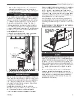
Begin assembly at 
the flue collar of the 
stove.  Insert the 
first crimped end 
into the stove’s flue 
collar, and keep 
each crimped end 
pointing toward 
the stove. (Fig. 4) 
Using the holes in 
the flue collar as 
guides, drill 3 mm 
(1/8”) holes in the 
bottom of the first 
section of chimney connector and secure it to the 

ST242

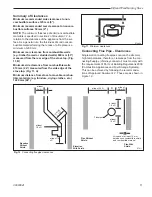
Chimney connector

12/13/99   djt

Flue Gas 

Direction

Toward 

Stove

ST242

Fig. 4 

 Chimney connector.

flue collar with three #10 x 1/2” sheet metal screws. 
Lift off the griddle, and shield the  stove’s surface 
between the griddle opening and the front of the flue 
collar to protect the finish when you drill the front 
hole.

• 

Fasten each joint between sections of chimney 
connector, including telescoping joints, with at least 
three (3) sheet metal screws. The pre-drilled holes in 
the top of each section of chimney connector serve 
as guides when you drill 3 mm (1/8”) holes in the 
bottom of the next section.

• 

Fasten the chimney connector to the chimney.  
Instructions for various installations follow. Figure 5 
illustrates the general layout of chimney connector 
parts.

• 

Be sure the installed stove and chimney connector 
are correct distances from nearby combustible mate-
rials.

NOTE:

 Special slip pipes and thimble sleeves that form 

telescoping joints between sections of chimney con-
nector are available to simplify installations. They often 
eliminate the need to cut individual connector sections. 
Consult your local dealer about these special pieces.

Securing the Single-wall Connector to a

Prefabricated Chimney

Follow the installation instructions of the chimney manu-
facturer exactly as you install the chimney. The manu-
facturer of the chimney will supply the accessories to 
support the chimney, either from the roof of the house, 
at the ceiling of the room where the stove is installed, or 
from an exterior wall.
Special adapters are available from your local dealer to 
make the connection between the prefabricated chim-
ney and the chimney connector. The top of such adapt-
ers attaches directly to the chimney or to the chimney’s 
ceiling support package, while the bottom of the adapter 
is screwed to the chimney connector.
These adapters are designed so the top end will fit out-
side the inner wall of the chimney, and the bottom end 
will fit inside the first section of chimney connector.

Securing the Single-wall Connector to a 

Masonry Chimney

Both freestanding masonry  chimneys and fireplace 
masonry chimneys may be used for your installation. 

Freestanding Installations 

If the chimney connector must pass through a com-
bustible wall to reach the chimney, follow the recom-
mendations in the Wall Pass-Through section that 
follows.  The opening through the chimney wall to the 
flue (the “breech”) must be lined with either a ceramic or 

Summary of Contents for Defiant 1945CE

Page 1: ...INSTALLED OPERATED AND MAINTAINED A HOUSE FIRE MAY RESULT TO REDUCE THE RISK OF FIRE FOLLOW THE INSTALLATION INSTRUCTIONS FAILURE TO FOLLOW INSTRUCTIONS MAY RESULT IN PROPERTY DAMAGE BODILY INJURY OR...

Page 2: ...of warmth beauty and comfort in your home At CFM Corporation we share that joy and appreciation for the hearth We assure you that your cast iron Vermont Castings stove has been made with the utmost c...

Page 3: ...rior using new technologies for ef cient combustion Americans purchased over a quarter million De ants as they rediscovered the common sense of heating with wood a home grown fuel with none of the pol...

Page 4: ...N T 826 mm 32 724 mm 28 788 mm 31 96 mm 3 546 mm 21 489 mm 19 464 mm 18 546 mm 21 3841 Defiant EU dimensions 7 06 768 mm 30 D E F I A N T 591 mm 23 489 mm 19 654 mm 25 C L 737 mm 29 Flue exit position...

Page 5: ...ng a chimney or house re Follow all instruc tions exactly and do not allow makeshift compro mises to endanger property and personal safety All local regulations including those referring to national a...

Page 6: ...t be operated with the front doors open Whatever the ue collar size an De ant may be vented into larger chimneys as well However chimneys with liners larger than 203 x 305 mm 8 x 12 may experience rap...

Page 7: ...Flue Gas Direction Toward Stove ST242 Fig 4 Chimney connector ue collar with three 10 x 1 2 sheet metal screws Lift off the griddle and shield the stove s surface between the griddle opening and the...

Page 8: ...above the replace opening Seal This Off ST243 thinble connection 12 13 99 djt Thimble Sleeve Chimney Connector Flue Keep sleeve end ush with ue tile ST243 Fig 6 The thimble made of either ceramic or...

Page 9: ...NOT CONNECT THE DEFIANT TO ANY AIR DIS TRIBUTION DUCT OR SYSTEM ST245 fireplace flex connector 12 99 Flexible Connector Mantel Shield Fireplace Adapter Kit Positive Connection ST245 Fig 8 Through the...

Page 10: ...De ant Costructional Hearth Dimensions as below At least 300 mm At least 150 mm or to a suitable heat resistant wall At least 150 mm Hearth Surface Free of Com bustible Material Perimeter should be c...

Page 11: ...A Minimum distance from stove to movable combus tible materials e g furniture drying clothes etc 1220 mm 48 ST486a Defiant EU Clearance Diagrams 10 06 A B ST486a Fig 11 Minimum clearances D at least 3...

Page 12: ...g the stove especially across rough surfaces can cause the legs to loosen or even break Storing the Handle Use the removable handle to open or close the doors After using it remove the handle so it wi...

Page 13: ...ew to attach the damper handle to the damper stub on the left side Attach the Primary Air Thermostat Handle The primary air thermostat handle is the smaller of the two black handles Secure the handle...

Page 14: ...e stove controls the amount of incoming air for starting maintaining and reviving a re More air entering the stove makes the re burn hotter and faster while less air prolongs the burn at a lower heat...

Page 15: ...nd air dried outside under cover for at least one year If hardwood is not available you can burn softwoods that include tamarack yellow pine white pine East ern red cedar r and redwood These should al...

Page 16: ...to get quite hot within a few minutes after a re is started the combus tor may stop working or the re may go out if the re dies down immediately as a result of the damper being closed Once the combus...

Page 17: ...e it is in use 3 Light the newspaper and close the door Gradually build up the re by adding a few 76 127 mm 3 5 di ameter splits If this is one of the rst few break in res let the re burn brightly and...

Page 18: ...sn t working Note that the catalyst is most likely to glow at its higher temperatures which it reaches when the rebox is in its lower range the catalyst is an after burner and the more waste fuel ther...

Page 19: ...erial Return the ash pan to its original position in the stove and close and latch the ash door Fig 31 Do not operate the stove with the ash door open This will result in over ring and could cause dam...

Page 20: ...the home An indoor chimney won t lose its heat to the outdoors so it takes less heat from the stove to heat it up and keep it warm Chimney Height The common wisdom tells us that a taller ue draws bet...

Page 21: ...sture meters available for rewood you can also judge your wood by its appearance and weight If you get it green lift a piece and get a sense of its weight it can lose a third or more of its weight as...

Page 22: ...crack a nearby window or door to enable the chimney to pull well that s a sign that you should install an outside air intake to bring combustion air directly to the stove An outside air adapter will a...

Page 23: ...ss with water or a cleaner made espe cially for this purpose Do not use abrasive cleaners Use cleaning agents sparingly and be sure to keep them off the outer surfaces of the stove Rinse the glass tho...

Page 24: ...he pressure screw from turning as you tighten the nut Re test the damper Tighten the Damper Handle as Needed A handle on the left side of the stove controls the damper The handle attaches to the dampe...

Page 25: ...he stove damper and once again check the smoke leaving the chimney You should see signi cantly more smoke when the stove damper is open and exhaust does not pass through the combustor However be caref...

Page 26: ...ing its effectiveness ST558 Inspect Catalytic element 4 11 00 Catalytic Ele ment Catalytic Access Panel ST558 Fig 38 Remove and inspect the catalytic element 5 Inspect the element for damage or degrad...

Page 27: ...need periodic replacement The sizes of replaceable gasket are listed below along with their applications Gasket Diameter And the Parts it Seals 5 16 The griddle to the stove top wire reinforced gaske...

Page 28: ...everyone out of the house Call the Fire Department Inspect the system every two weeks during the heat ing season as part of a regular maintenance schedule To inspect the chimney let the stove cool com...

Page 29: ...alyst is still there it is covered or masked by the contaminant and cannot function To avoid this situation it is important not to burn any thing in your De ant that is a source of these contami nants...

Page 30: ...roper clearance between chimney and nearby combustibles less than 51 mm 2 check local codes K Loose or leaky cleanout door For a replace F Improper clearance between smoke chamber and framing material...

Page 31: ...9 85 86 87 70 78 71 88 59 90 52 91 91 CFM Corporation reserves the right to make changes in design materials speci cations prices and discontinue colors and products at any time without notice De ant...

Page 32: ...rt 1300642 58 Ashpan Bracket 30001908 59 Primary Air Valve Assy 5000024 60 Primary Air Frame3 1307411 61 Primary Air Rod3 1600058 62 Primary Air Valve3 1307412 63 Thermostat Handle Wood 1600660 64 Air...

Page 33: ...0001612 1320621 30001616 Suede Brown 30002578 30002574 30002573 30002575 30002583 30002580 Vermont Classic Green 30002997 30002993 30002992 30002994 30002991 30002998 Shell Enamel Parts De ant Enamel...

Page 34: ...34 Defiant Woodburning Stove 30003841...

Page 35: ...te 3 Date of failure of catalyst 4 Any relevant information or circumstances regarding determina tion of failure 5 In addition the owner must return the failed catalyst Exclusions Limitations 1 This w...

Page 36: ...CFM Corporation 2695 Meadowvale Blvd Mississauga Ontario Canada L5N 8A3 800 668 5323 www cfmcorp com CFM Corporation...

Reviews: