background image

11

Omni 3210 Installation Guide

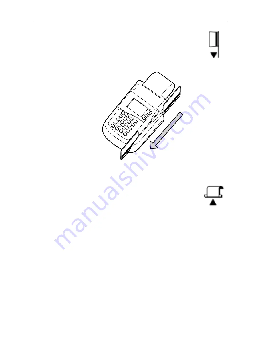
A


magnetic stripe card reader

, built in to the 

right side of the terminal. A graphical icon, 
shown to the right, indicates the proper card 
position and swipe direction (see Figure 6).

Figure 6

Using the Magnetic Stripe Card Reader

A


thermal printer

, integrated into the upper 

part of the terminal. In the top left corner of the 
terminal is a small, green “power-on” and “no 
paper” indicator light, and a paper feed button. 
An icon, shown to the right, indicates the 
location and function of the paper feed button.

Connection Ports on the Back Panel

If you turn the terminal around and view it from the back, 
looking below and to the right of the paper roll holder, you will 
notice five modular jacks, or ports (see Figure 7). These ports, 
described in left-to-right order below, let you connect the Omni 
3210 to a telephone line, up to two optional peripherals, and an 
electrical power source.

Summary of Contents for Omni 3210

Page 1: ...Omni 3210 Installation Guide...

Page 2: ...advised of the possibility of such damages Product Changes VeriFone reserves the right to change update or make obsolete any product changes at any time and without notice Document Title Omni 3210 Ins...

Page 3: ...atures 10 Step 4 Connect the Terminal to a Telephone Line 13 Step 5 Connect Optional Device s 18 Step 6 Connect the Terminal Power Pack 23 Step 7 Install a Paper Roll in the Printer 25 Maintaining the...

Page 4: ...Omni 3210 Installation Guide 4...

Page 5: ...of Sale Terminal The Omni 3210 terminal s internal PIN pad eliminates the need to purchase and connect an external PIN pad and also saves valuable countertop space An optional swivel stand facilitate...

Page 6: ...arge back lit display with graphics capability a high speed integrated thermal printer a triple track magnetic stripe card reader two telephone ports to eliminate the expense of a second phone line ad...

Page 7: ...onal swivel stand make sure there is enough space on the countertop or table so the clerk cashier can rotate the terminal freely on the stand to allow cardholders to easily enter their PIN number for...

Page 8: ...c motors Step 2 Unpack the Shipping Carton Carefully inspect the Omni 3210 shipping carton and its contents for any damage or tampering see Figure 3 and Figure 4 To unpack the shipping carton 1 Remove...

Page 9: ...ears damaged or to have been tampered with immediately notify the shipping company and your VeriFone distributor or service provider Caution Do not use a terminal that has been damaged or tampered wit...

Page 10: ...ou you will notice the following features In the center of the terminal a display screen with a non removable clear protective lens 24 keys arranged in groups see Figure 5 A 12 key telephone style key...

Page 11: ...he terminal is a small green power on and no paper indicator light and a paper feed button An icon shown to the right indicates the location and function of the paper feed button Connection Ports on t...

Page 12: ...t the Omni 3210 to a telephone base unit to configure an optional pass through telephone line connection The second telephone line port is identified by a jack shaped Telco icon shown to the right You...

Page 13: ...Power port is identified by the electrical power icon shown to the right Step 4 Connect the Terminal to a Telephone Line You can connect the Omni 3210 to a telephone line in one of two ways direct or...

Page 14: ...r leased line There are however several disadvantages to using a pass through connection You cannot make a normal call while the terminal is processing a transaction or when a remote host computer is...

Page 15: ...n you want Set Up a Direct Telephone Line Connection To set up a direct telephone line connection for your Omni 3210 terminal follow these steps refer to Figure 8 1 Insert the connector on one end of...

Page 16: ...hown to the right 2 Insert the connector on the other end of the first telephone line cable into a nearby RJ 11 type telephone company wall jack 3 Insert the connector on one end of the second telepho...

Page 17: ...d To set up a direct connection using the pigtail cable 1 Insert the connector on one end of the telephone line cord into the modular RJ 11 type jack located inside the square shaped female end of the...

Page 18: ...wands external PIN pads and an external printer Brief descriptions of how to connect various devices to the Omni 3210 are provided below Caution Before connecting any peripheral device turn off power...

Page 19: ...the round mini DIN type connector on one end of the serial cable into the TERM i e Terminal port on the back of the check reader 2 Insert the RJ45 type connector on the other end of the serial cable i...

Page 20: ...the RJ 11 type plug on one end of the cable into the modular jack on the device 2 Insert the larger RJ 45 type plug on the other end of the serial cable into the Bar Code PIN Pad port on the back pane...

Page 21: ...13 and Figure 14 To connect an external PIN pad to the Omni 3210 terminal 1 If necessary insert the small RJ 11 type modular plug on one end of the PIN pad cable into the modular jack on the PIN pad...

Page 22: ...onnect an External VeriFone Printer The Omni 3210 terminal comes with an integrated thermal printer The Omni 3210 can also support an external VeriFone printer the Printer 250 This external printer ca...

Page 23: ...nector on the end of the other power pack cable into the terminal s Power port 1 Plug the three pronged plug on the end of one power pack cable into an electrical power outlet see Figure 15 Note To pr...

Page 24: ...e power port The locked icon is shown to the right To remove the power cable from the terminal and to disconnect the terminal from its power source turn the connector to the right toward the unlocked...

Page 25: ...t case and or packaging Do not use the adapter if the cord becomes damaged Do not attempt to service the adapter There are no serviceable parts inside Replace the unit if it is damaged or exposed to e...

Page 26: ...in the Omni 3210 printer Store thermal paper in a dry dark area Handle thermal paper carefully impact friction temperature humidity and oil affect the color and storage characteristics of the paper N...

Page 27: ...the terminal by lifting up on the back of the cover The two ridges on each side of the black plastic cover show you where to grasp it 3 Remove the protective strip from a new roll of paper and cut a c...

Page 28: ...ither end of the serrated metal strip and then lightly pushing down on the back of the cover until it snaps into place Remember to lift up the end of the paper roll when replacing the paper roll cover...

Page 29: ...starts automatically and then stops after a few seconds 3 When you see the test printout release the paper feed button The complete test printout which shows printer information and repeating charact...

Page 30: ...or rubber parts Do not spray cleaners or other solutions directly onto the keypad or display lens Cleaning the Printer Every few months check and thoroughly clean the integrated thermal printer 1 Be...

Page 31: ...re some examples of possible problems and steps you can take to quickly resolve them Display Does Not Show Correct or Readable Information 1 Check all cable connections 2 Check the electrical outlet o...

Page 32: ...ves its power directly from the Omni 3210 terminal The green LED indicator light in the upper left corner of the terminal should be On 2 If the green LED indicator is blinking Off and On the printer i...

Page 33: ...oblem is not a defective card 2 Make sure you are swiping cards properly With the Omni 3210 card reader the black magnetic stripe on the back of the card should face downward and to the right 3 Proces...

Page 34: ...een opened by an unauthorized party key data that is necessary to process PIN based transactions using the internal PIN pad may have been erased 3 If the Tamper Warning label has been breached or remo...

Page 35: ...ur VeriFone distributor or service provider Telephone Connection Does Not Work Properly 1 Check the telephone line cord and all telephone connections 2 If you are using a pass through connection check...

Page 36: ...bottom and indicates if an unauthorized party has opened the terminal case Opening the case will make the terminal inoperable and void the product warranty To return a terminal for service follow thes...

Page 37: ...roduct ID numbers and the Serial Number of the terminal s you are returning for service or repair Shipping documentation such as airbill numbers which you can use to trace the shipment Figure 17 Infor...

Page 38: ...V DC 1 2A Environmental Operating temperature 0 to 40 C 32 to 104 F Storage temperature 18 to 66 C 0 to 150 F Relative humidity 15 to 95 no condensation Dimensions Height 75 mm 2 95 inches Width 148 m...

Page 39: ...o the VeriFone Part Number in the left hand column Note Cables with XX Part Number suffixes come in a variety of lengths Download Cables 05651 XX MOD10 MOD10 terminal to terminal 26263 XX 02XXX MOD10...

Page 40: ...r Pack 05790 03 Input 100 250 V 50 60 Hz 1 2 A Output DC 25 5 V 1 57 A Thermal Printer Paper CRM0039 01 20 High grade thermal printer paper 58 mm 2 25 inch width 20 rolls CRM0039 01 50 High grade ther...

Page 41: ...41 Omni 3210 Installation Guide 21919 Omni 3XXX Swivel Stand Quick Installation Guide 21920 Omni 3210 Installation Guide 22295 Omni 3200 3210 Reference Manual 22296 Omni 3200 3210 Programmer s Guide...

Page 42: ...Omni 3210 Installation Guide 42...

Page 43: ...Gateway Place Ste 600 San Jose CA 95110 USA Ph 408 232 7800 Fax 408 232 7811 Web www verifone com Omni 3210 Installation Guide VeriFone Part Number 21920 Revision A 2001 VeriFone Inc All rights reser...

Reviews: