


Cabinet Instal lation
I-Ga te 4000 P R O Ins tall ation
5-12
Veraz Networks Inc. Proprietary
02041802-05
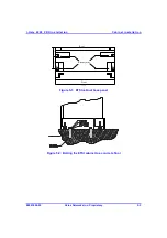
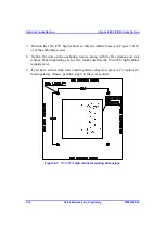
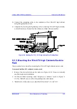
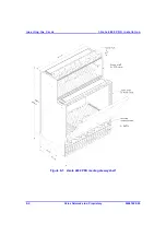
5. Using a 10 mm drill, make holes 60 mm deep, so the screw anchors touch the
concrete floor, (marked out in the previous step) as shown in Figure 5-9.
6. Using an air compressor or similar device, clean the debris from the holes.
7. Insert the screw anchors into the holes on the concrete floor. Then, using light
strokes, hammer the screw anchors deeper into the holes until they are flush with
the floor.
8. Cut the threaded rods to a size equal to the distance between the concrete floor
and the upper side of the floating floor, plus an additional 60 mm.
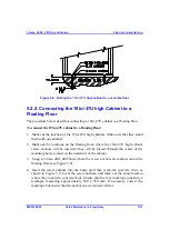
9. Screw an M8 nut, spring washer and flat washer to a depth of 50 mm from the
top of the threaded rod. Insert the top of the threaded rod with the nut into the
screw anchor in the concrete floor. Tighten the nuts on the screw anchors, as
shown in Figure 5-9.
10. Screw two nuts and a flat washer on the threaded rod, to a height of 20 mm
under the floating floor.
11. Put the floating floor tiles on top of the threaded rods. Make sure that they are
correctly positioned. Drill holes at the spot where the ends of the threaded rods
protrude from the floating floor.
12. Screw in the two nuts that were placed on the threaded rods until the flat washers
are less than 2 mm from the bottom of the floating floor. Secure the two nuts
together by tightening each one.
13. Slide the tile over the 4 threaded rods and verify that the nuts support the tile.
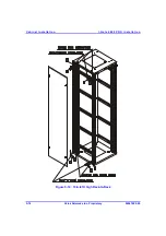
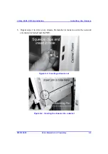
14. Position the 19in./47U high cabinets over the screw anchors.
15. Tighten the nuts, including the flat washers and the spring washers, of the screw
anchors. Make sure that the 19in./47U high cabinet remains level. If necessary,
repeat the leveling and tightening procedures.


