background image

5.5 I

NSTALLING

I

NSULATED

F

LEXIBLE

D

UCTS

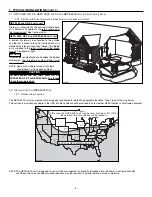
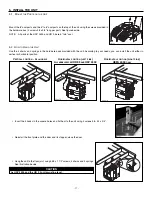
Use the following procedure for connecting the insulated flexible ducts to the Tandem® transition* (

EXHAUST AIR TO OUTSIDE and

FRESH AIR FROM OUTSIDE).
NOTE: If the joist are perpendicular to the ducts, or if the connection to the exterior hood is in a limited area, your installation will need 

two exterior hoods instead of one. In this case, do not use the Tandem® transition. Identify each insulated duct. For fresh air from 
outside duct, use the blue sticker dots (one dot at each end). For exhaust air to outside duct, use the red sticker dots (one dot at each
end). (No dots for HRV 2500 and HR 2.5 units.) Then, go to point 5.5.2 and refer to the optional single hood enclosed instructions.

*Patent pending.

5.5.1  C

ONNECTION TO

T

ANDEM

®

TRANSITION

1.

For each duct, pull back the insulation to expose the interior flexible duct.

2.

Connect the interior flexible duct to the smaller part of the Tandem® transition (5’’ oval) using a tie wrap.

NOTE: If you are using a 6’’ diameter insulated duct, use the bigger part of the Tandem® transition (6’’ oval).

3.

Pull the insulation over the joint. Pull the vapor barrier over the insulation.

4.

Apply duct tape gently to the joint in order to make an airtight seal. See figures below.

Identify each insulated duct. For fresh air from outside duct, use the blue sticker dots (one dot at each end). For exhaust air to outside
duct, use the red sticker dots (one dot at each end).

Be careful to identify the exhaust air to outside duct (red dot) at the upper

section of the transition.

(No dots for HRV 2500 and HR 2.5 units.)

5.5.2  C

ONNECTION TO THE

5’’

TO

6’’

OVAL PORTS OF THE UNIT

Use the following procedure for connecting the insulated flexible ducts to the 5’’ to 6’’ oval ports of the unit (

EXHAUST AIR TO OUTSIDE

and 

FRESH AIR FROM OUTSIDE).

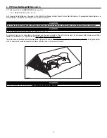
1.

Pull back the insulation to expose the flexible duct.

2.

Connect the interior flexible duct to the smaller part of the port (5’’ oval) using a 24’’ tie wrap.

NOTE: If you are using a 6’’ diameter insulated duct,  use the bigger part of the port (6’’ oval).

3.

Pull the insulation over the joint and tuck it between the inner and outer rings of the port.
Pull the vapor barrier over the insulation and over the outer ring of the port.

5. INSTALL THE  UNIT 

(CONT’D)

CAUTION

Make sure the vapor barrier on the insulated ducts does not tear during installation.

VJ0025

VJ0022

VJ0023

VJ0024

1

2

3

4

E

XHAUST AIR TO OUTSIDE

DUCT ON TOP

VJ0017

VJ0016

VJ0018

- 15 -

Summary of Contents for HEPA 3000

Page 1: ...OMEOWNER HOMEOWNER USE AND CARE INFORMATION ON PAGES 18 TO 20 READ AND SAVE THESE INSTRUCTIONS 04313 rev F M O D E L S VB0064 HEPA 3000 HF 3 0 HEPA 4000 HRV 2500 HR 2 5 Patents pending NOTES 1 HRV 250...

Page 2: ...et 4 Installation must be done in accordance with all applicable codes and standards including fire rated construction codes and standards 5 This unit is not designed to provide combustion and or dilu...

Page 3: ...HANG THE UNIT 11 5 3 PLANNING OF THE DUCTWORK 12 5 4 INSTALLING NON INSULATED DUCTS AND REGISTERS 12 5 4 1 STAND ALONE SYSTEM 12 13 5 4 2 CENTRAL DRAW POINT 13 14 5 4 3 RETURN TO RETURN 14 5 5 INSTALL...

Page 4: ...Fresh filtered air is supplied by the register located in the lowest liveable level See figure at right 1 1 2 CENTRAL DRAW POINT CONNECTION TO A FORCED AIR SYSTEM VH0040 ALL UNITS For this type of ins...

Page 5: ...RRISBURG SACRAMENTO DENVER TOPEKA DETROI T INDIANAPOLIS SANTA FE SPRINGFIELD OKLAHOMA CITY PHOENI X COLUMBUS NASHVILLE ATLANTA BATON ROUGE AUSTIN COLUMBI A RALEIG H WASHINGTON HARTFORD BOSTON REN O HE...

Page 6: ...of the forced air unit To avoid cross contamination and achieve the highest efficiencies the forced air system blower must always be ON See figure below NOTE Home with multiple forced air systems shou...

Page 7: ...g the minimum clearance needed to open the door completely 22 5 15 75 572 mm 400 mm VD0117 VD0116 22 559 mm NOTE A minimum of 8 203 mm clearance from any obstruction on top of the unit is required for...

Page 8: ...ction installation only to cut ductwork Aluminum duct tape for plenum connection installation only Jig saw Caulking gun and caulking For HRV 2500 and HR 2 5 units the installation kit is 15273 For HEP...

Page 9: ...s the other end of the cable through the wall Reinstall the cover plate Using wall anchors and provided screws mount the wall control on the wall See illustrations below 1 Wall anchors 4 Control 1 Out...

Page 10: ...d front plate of the unit at this time they need to be removed for preparing the unit to be hung 2 When using the wall control the main switch on the unit must always be positioned to NORMAL REMOTE 6...

Page 11: ...ORTS ON THE UNIT Mount the 8 oval ports and the 5 to 6 oval ports on the top of the unit using the screws provided in the hardware box 4 screws 8 x 3 4 long per port See figure beside NOTE All ports o...

Page 12: ...e air circulation Keep in mind that the filtered air register must be located as far as possible from the stale air register If desired you can install another register sold separately Install the reg...

Page 13: ...ystem described in point 5 4 1 Fresh Filtered air ductwork Return side connection HRV 2500 AND HR 2 5 UNITS ONLY Locate the opening for fresh filtered air ductwork on the forced air unit at a minimum...

Page 14: ...1 1 3 AND 1 2 2 Fresh Filtered air ductwork Return side connection Same as for Central Draw Point described in point 5 4 2 Stale air ductwork Return side connection ALL UNITS Locate the stale air duc...

Page 15: ...the vapor barrier over the insulation 4 Apply duct tape gently to the joint in order to make an airtight seal See figures below Identify each insulated duct For fresh air from outside duct use the blu...

Page 16: ...exterior hood must be installed at a minimum distance of 18 inches 457 mm from the ground See illustration beside 5 6 3 CONNECTING TANDEM TRANSITION TO THE DUAL EXTERIOR HOOD 1 Using a jig saw cut a 6...

Page 17: ...the 2 plastic drain fittings 1 using the gaskets 2 and nuts 3 as shown Close the door VO0027 27 686 mm 7 178 mm 3 Cut 2 sections of plastic tubing one 7 178 mm long and one 27 686 mm long and attach...

Page 18: ...from a wood stove through out the house or the fresh air from a cooling system 6 CONTROLS OFF UNIT IS OFF AND DOOR IS UNLOCKED NORMAL REMOTE UNIT IS OPERATING ON NORMAL SPEED THIS IS THE RIGHT POSITI...

Page 19: ...cuum to remove most of the dust Let it soak in a solution of warm water and mild soap Rinse thoroughly and let dry before reinstalling it 5 Clean the inside walls of the unit with a clean damp cloth t...

Page 20: ...control for HV 2 5 and HF 3 0 units only All listed parts are available where you have bought your unit NOTE Please note that parts not listed are not available those parts require assembly knowledge...

Reviews: