


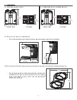


9.
Using a small rod, pierce a hole through the unit at the end of the wire channel in front of
the unit. (See picture beside.) Splice back the end of the cable to access the 4 wires.
Remove the insulated sleeve of each wire ends. Insert the end of the cable through the
unit, using the small hole previously done. From the top right front hole of the unit, pull on
the wire.
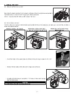
10.
In order to access the unit PCB terminals, remove the side door located on the electrical
box and punch out its knock out. Run the cable through the knock-out hole and connect
each wire in their corresponding terminal (YELLOW in ‘’Y’’, RED in ‘’R’’, GREEN in ‘’G’’and
BLACK in ‘’B’’).
NOTE: Push forward slightly on the little tabs (
1
) to ease insertion of each wires.
See picture beside.
11.
Reinstall the side door on the electrical box.
12.
Route the wire through its channel. See picture beside.
NOTES: 1. The wall control installation is now done. Do not reinstall the door and front plate of the unit at this time; they need to be
removed for preparing the unit to be hung.
2. When using the wall control, the main switch on the unit must always be positioned to NORMAL/REMOTE.
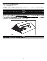
6.
Route the cable to the unit location.
7.
Turn the unit switch knob to OFF position in order to unlock the door. Unlatch the door and
open it. If required, the door can be removed. To do so, remove the stopper (
A
) located on the
right side of the door hinge. Then, hold the door and hit with your palm its left side. Slide the
door to the right to disengage it from the unit.
8.
Using a screwdriver, remove the 2 retaining screws of the front plate and carefully remove the front
plate from the unit.
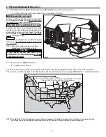
CAUTION
Keep control low voltage wiring at least 1 foot (305 mm) away from motors, lightning ballast, light dimming circuit and power
distribution panel. Do not route control wiring along with house power wiring. Avoid poor wiring connections. Failure to
follow these practices can introduce electrical interference, which can cause erratic control operations.
VO0019
VD0088
4. WALL CONTROL INSTALLATION
(CONT’D)
VD0089
VE0049
1
- 10 -
VD0170
A


