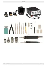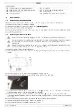
VTSSD4
V. 01
–
15/05/2014
7
©Velleman nv
8.
Switching On and Off
To switch the device on, set the power switch
[1]
in the on position (1). The switch lights up. The device
activates all functions (soldering, desoldering, and hot air) and starts heating up. The heating
indications
[10,15,20]
light up during warming up. The displays
[9,14,19]
show the temperature.
To switch the device off, set the power switch
[1]
in the off position (0).
Caution!
After switching off,
leave the power cord plugged in
for a few minutes. When you switch off the
unit, the automatic cooling function blows cooling air through the heater pipe for a short period. This protects
the heater from damage and extends its lifetime. Do not disconnect the mains plug during this cooling process.
Wait until the cooling process has stopped, then disconnect the power plug. The device uses a small amount of
electrical power, even if it is switched off.
Switching off Individual Functions
When you switch on the device, it activates all functions: soldering, desoldering, and hot air. However, to save
power, you can switch off individual functions. Proceed as follows:
1.
To switch off a function, press the corresponding SET and
▼
buttons simultaneously. For example, to switch
off desoldering, press buttons
[16]
and
[13]
. The corresponding temperature display shows
“—
—
—”
.
2.
To reactivate a function, press the corresponding
▲
button.
9.
Using the Soldering/Desoldering Iron
9.1
Parameter Settings
The parameter settings for soldering and desoldering are identical. Use the buttons that correspond with the
function that you want to set. For soldering, use buttons 7
–
11. For desoldering, use buttons 12
–
16.
1.
Switch on the station
[1]
.
2.
Press and hold the SET button for at least 5
seconds until “—
—
—” flashes on the display. Use t
he
▲
button
to enter the password “010” (default) and press the SET button to enter the setup menu. An
incorrect password will return the station to normal operation mode (temperature indication).
The display shows “F
-
0”.
3.
Press the
▲
or
▼
button to select a mode. If you do not press a button within 15 seconds, the device
returns to normal operation mode.
F-0
: exit menu mode
Press the SET button when the display shows F-0 to exit the setup menu and return to normal operation
mode.
F-1
: password mode
If password mode is enabled, you cannot change the temperature settings on the station unless you know
the password.
Press the SET button once to enter password mode. Press the
▲
or
▼
button to switch between 000
(password mode disabled) and 100 (password enabled). Press the SET button to return to the setup menu.
F-2
: temperature correction mode
If the displayed temperature deviates from the actual temperature of the tip, you can calibrate the display
here.
Press the SET button once to enter temperature correction mode. Press the
▲
or
▼
button to enter a
correction factor for the temperature (
–
99 °C to +99 °C;
–
178 °F to +178 °F). For example, if the display
shows 300 °C but the actual temperature is only 290 °C, add 10 °C to the shown correction value. If the
current correction value is 00, change it to 10. If the current correction value is
–
20, set it to
–
10. If the
current correction value is 20, set it to 30.
A minus sign in front indicates a negative value. Press the SET button to return to the setup menu.
F-3
: sleep/power off mode
If you enable the sleep/power off mode, the device automatically lowers the iron temperature after
20 minutes of inactivity (sleep mode). After 40 minutes of inactivity, the power to the iron is shut off
(power off mode).
Note:
you can set the sleep/power off mode individually for the soldering and desoldering iron.
Press the SET button once to enter sleep/power off mode. Press the
▲
or
▼
button to switch between 000
(sleep/power off mode disabled) and 100 (sleep/power off mode enabled). Press the SET button to return
to the setup menu.
In sleep mode, the device lowers the soldering iron temperature to 150 °C (302 °F), and the desoldering
iron temperature to 200 °C (392 °F). The display flashes and shows the lowered temperature.
Note:
by default, sleep/power mode is disabled.


