background image

HAA55_v2


VELLEMAN 

- 2 -

HAA55 – GLASS BREAK DETECTOR WITH PIR SENSOR 


1. Introduction 


To all residents of the European Union 

Important environmental information about this product 

This symbol on the device or the package indicates that disposal of the device after its lifecycle could harm 

the environment. 

Do not dispose of the unit (or batteries) as unsorted municipal waste; it should be taken to a specialized 

company for recycling. 

This device should be returned to your distributor or to a local recycling service. 

Respect the local environmental rules. 

If in doubt, contact your local waste disposal authorities. 


Thank you for choosing Velleman! Please read the manual thoroughly before bringing this device into service. If the 

device was damaged in transit, don't install or use it and contact your dealer. Damage caused by disregard of certain 

guidelines in this manual is not covered by the warranty and the dealer will not accept responsibility for any ensuing 

defects or problems. 


2. Mounting 


Remark: Choose an installation spot out of direct sunlight and with a constant temperature. Do not install the 

HAA55


facing a metal door. 


Open the housing by pushing the upper slot using a flat-headed screwdriver. 


Remove the PCB by spreading the two tabs on either side of the board. 


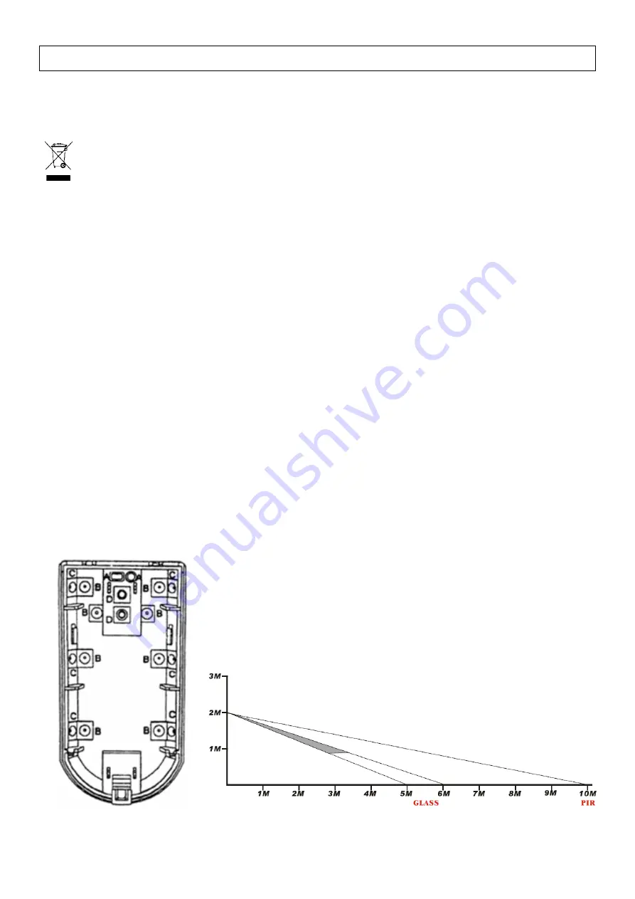
Punch the necessary wiring holes in the housing (see fig. 1). 


Pull the wires through the punched holes and mount the back of the housing onto the wall or ceiling using the 

necessary screws and/or bracket. 


Reinstall the PCB into the housing. 


Connect the wires to the PCB using the terminal block (see “

3. PCB

”). 


Close the housing. 


A. wire hole 

B. mounting hole 

C. mounting hole (corner) 

D. bracket hole


Coverage pattern – side view


Summary of Contents for HAA55

Page 1: ...GLASBREUKDETECTOR MET PIR SENSOR D TECTEUR DE BRIS DE VERRE AVEC CAPTEUR PIR DETECTOR DE ROTURA DE CRISTAL CON DETECTOR PIR GLASBRUCHMELDER MIT PIR SENSOR USER MANUAL GEBRUIKERSHANDLEIDING NOTICE D EM...

Page 2: ...in transit don t install or use it and contact your dealer Damage caused by disregard of certain guidelines in this manual is not covered by the warranty and the dealer will not accept responsibility...

Page 3: ...10 M W adjustment connect with controlling unit alarm will sound when the front cover is opened 4 Jumper Setting Place the bridge onto the desired pins JP1 OFF LED is disabled ON LED is enabled JP2 pu...

Page 4: ...ousing Move in front of the detector The yellow and the red LED should light respectively 7 Technical Specifications Power Supply 9 12VDC Current Consumption Standby 14mA Operational 22mA Detection Di...

Page 5: ...raadpleeg uw dealer De garantie geldt niet voor schade door het negeren van bepaalde richtlijnen in deze handleiding en uw dealer zal de verantwoordelijkheid afwijzen voor defecten of problemen die hi...

Page 6: ...ling sluit aan op controle eenheid alarm luidt wanneer de behuizing wordt geopend 4 Instellen van de jumpers Plaats het bruggetje over de gewenste pinnen JP1 OFF led is uitgeschakeld ON led is ingesch...

Page 7: ...Beweeg voor de sensor De gele respectievelijk de rode led licht op 7 Technische specificaties Voeding 9 12VDC Stroomverbruik Stand by 14mA In werking 22mA Waarnemingsbereik PIR 10m Glas 6m Waarneming...

Page 8: ...il Si l appareil a t endommag pendant le transport ne pas l installer et consulter votre revendeur La garantie ne s applique pas aux dommages survenus en n gligeant certaines directives de cette notic...

Page 9: ...age M W raccorder l unit de commande l alarme retentit lorsque le bo tier est ouvert 4 Param trage des cavaliers Glisser le pont sur les broches souhait es JP1 OFF LED d sactiv e ON LED activ e JP2 r...

Page 10: ...ur et bouger Les LED jaune et rouge s allument respectivement 7 Sp cifications techniques Alimentation 9 12VCC Consommation de courant Veille 14mA Service 22mA Port e de d tection PIR 10m Bris de verr...

Page 11: ...p ngase en contacto con su distribuidor Da os causados por descuido de las instrucciones de seguridad de este manual invalidar n su garant a y su distribuidor no ser responsable de ning n da o u otro...

Page 12: ...W con ctelo a la unidad de control la alarma suena si se abre la caja 4 Ajustar los cables de puente Deslice el puente sobre los polos deseados JP1 OFF LED desactivado ON LED activado JP2 ajustar la a...

Page 13: ...Vuelva a cerrar la caja P ngase frente al sensor y mu vase El LED amarillo y rojo se ilumina 7 Especificaciones Alimentaci n 9 12VCC Consumo de corriente Standby 14mA En funcionamiento 22mA Alcance d...

Page 14: ...er t nicht und wenden Sie sich an Ihren H ndler Bei Sch den die durch Nichtbeachtung der Bedienungsanleitung verursacht werden erlischt der Garantieanspruch F r daraus resultierende Folgesch den berni...

Page 15: ...Kontakt mit der Kontrolleinheit Der Alarm ert nt wenn das Geh use ge ffnet wird 4 Die Steckbr cken einstellen Stellen Sie die Br cke ber die gew nschten Pole JP1 OFF LED ist ausgeschaltet ON LED ist...

Page 16: ...ellen Sie JP2 auf 4s Stellen Sie JP3 auf ON Schlie en Sie das Geh use Bewegen Sie vor dem Sensor Die gelbe und rote LED leuchten 7 Technische Daten Stromversorgung 9 12VDC Stromverbrauch Standby 14mA...

Reviews: