Y
ou can
fi
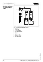
nd the electrical connection of
VEGATOR
631
E
x in the
operating instructions manual of the corresponding signal conditioning
instrument
.
L
ine monitoring
W
ith
E
x versions
,
this
220
k
Ω
resistor is already integrated ex factory in
the connection housing of the probe
.
T
he
E
x measuring system
(
max
.
and ground connection cable of the probe to the signal conditioning
instrument
)
is generally monitored for line break
.
Y
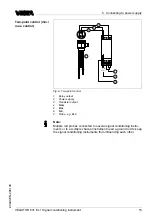
ou can set mode
A
or
B
by means of the selection switch
.
M
ode
A
P
referrably as over
fl
ow protection
,
compulsory as over
fi
ll protection
.
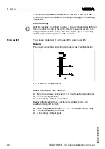
1
2 3
F
ig
.
14
:
M
ode
A
-
O
ver
fi
ll protection
M
eans with covered max
.
electrode
:
l
R
elay deenergises
,
connection
12
-
13
is connected through relay
l
T
ransistor output blocks
l
C
ontrol lamp
-
O
utput extinguishes
M
eans with uncovered max
.
electrode
(
level detection
)
or min
.
electrode
(
two
-
point control
):
l
R
elay energises
,
connection
12
-
14
is connected through relay
l
T
ransistor output is conductive
l
C
ontrol lamp
-
O
utput lights
M
ode switch
22
VEGATOR
631
E
x
•
S
ignal conditioning instrument
6
S
et up
23440
-
EN
-
090130

