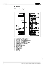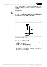
B
efore setting up
E
x versions
,
make sure the
E
x separating chamber is
plugged
(
above the sensor terminals
).
T
he pins for type and
E
x coding
must also be inserted correctly
.
5
.
3
W
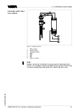
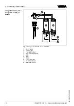
iring plan
1 2
5
4
1
3
2
4
5 6
9
13
10
14
12
7 8
L
(+)
N
(–)
1
2
3
6
F
ig
.
5
:
L
imit level measurement
1
R
elay output
2
P
ower supply
3
T
ransistor output
4
M
ass
5
max
.
6
P
robe
,
e
.
g
.
EL
1
L
imit level measurement
14
VEGATOR
631
E
x
•
S
ignal conditioning instrument
5
C
onnecting to power supply
23440
-
EN
-
090130


