background image

Printing date:

VEGA Grieshaber KG

Am Hohenstein 113

77761 Schiltach

Germany

45300-EN-170724

All statements concerning scope of delivery, application, practical use and operat-

ing conditions of the sensors and processing systems correspond to the information 

available at the time of printing.

Subject to change without prior notice

© VEGA Grieshaber KG, Schiltach/Germany 2017

Phone +49 7836 50-0

Fax +49 7836 50-201

E-mail: [email protected]

www.vega.com

Summary of Contents for VEGADIS 82

Page 1: ...Operating Instructions External display and adjustment unit for 4 20 mA HART sensors VEGADIS 82 4 20 mA HART Document ID 45300 ...

Page 2: ...ower supply 5 1 Preparing the connection 15 5 2 Connection technology and steps 16 5 3 Wiring plan 18 5 4 Connection HART standard 18 5 5 Connection HART multidrop 19 5 6 Connection signal conditioning instrument four wire sensor 19 5 7 Connection example 21 5 8 Switch on phase 21 6 Set up with the display and adjustment module 6 1 Short description 22 6 2 Insert display and adjustment module 22 6...

Page 3: ...smount 9 1 Dismounting steps 54 9 2 Disposal 54 10 Supplement 10 1 Technical data 55 10 2 HART communication 58 10 3 Dimensions 59 10 4 Industrial property rights 62 10 5 Trademark 62 Safety instructions for Ex areas Take note of the Ex specific safety instructions for Ex applications These instructions are attached as documents to each instrument with Ex approval and are part of the operating ins...

Page 4: ...available to these personnel and put into practice by them 1 3 Symbols used Information tip note This symbol indicates helpful additional information Caution If this warning is ignored faults or malfunctions can result Warning If this warning is ignored injury to persons and or serious damage to the instrument can result Danger If this warning is ignored serious injury to persons and or destructio...

Page 5: ...nt can be impaired 2 4 General safety instructions This is a state of the art instrument complying with all prevailing regulations and directives The instrument must only be operated in a technically flawless and reliable condition The operator is responsi ble for the trouble free operation of the instrument When measuring aggressive or corrosive media that can cause a dangerous situation if the i...

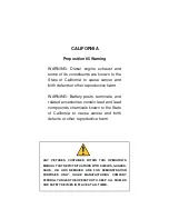
Page 6: ...gnetic compatibility of equipment NE 53 Compatibility of field devices and display adjustment components For further information see www namur de 2 7 Installation and operation in the USA and Canada This information is only valid for USA and Canada Hence the follow ing text is only available in the English language Installations in the US shall comply with the relevant requirements of the National...

Page 7: ...ollowing instrument data on our homepage Article number HTML Delivery date HTML Order specific instrument features HTML Operating instructions at the time of shipment PDF Go to www vega com Instrument search serial number Enter the serial number As an alternative you can access these data via your smartphone Download the smartphone app VEGA Tools from the Apple App Store or the Google Play Store S...

Page 8: ...he instrument is looped directly into the 4 20 mA HART signal line at any location Separate external energy is not necessary VEGADIS 82 also operates exclusively as an indicating instrument in a 4 20 mA current loop The instrument is particularly designed for VEGAPULS WL 61 VEGAWELL 52 These sensors have no own display adjustment The housing of VEGADIS 82 contains a filter element for ventilation ...

Page 9: ...ia PC with PACTware 1 Voltage supply Signal output sensor 2 VEGADIS 82 3 VEGACONNECT 4 4 20 mA HART signal cable 5 Sensor 6 PC with PACTware DTM 4 20 mA mode when connected to a 4 20 mA signal cable VEGADIS 82 operates exclusively as a display instrument Adjustment range Indication scaling VEGADIS 82 HART mode when operated with a 4 20 mA HART sensor the VEGADIS 82 operates as display and HART adj...

Page 10: ...y at receipt Ascertained transit damage or con cealed defects must be appropriately dealt with Up to the time of installation the packages must be left closed and stored according to the orientation and storage markings on the outside Unless otherwise indicated the packages must be stored only under the following conditions Not in the open Dry and dust free Not exposed to corrosive media Protected...

Page 11: ...ware PACTware with VEGA DTM is required You can find further information in the operating instructions Interface adapter VEGACONNECT Document ID 32628 The electronics module is a replacement part for the display and adjustment instrument VEGADIS 82 A separate version is available for each type of signal output You can find further information in the operating instructions Elec tronics module VEGAD...

Page 12: ...ere high humidity is expected e g through cleaning processes and on cooled or heated vessels To maintain the housing protection make sure that the housing lid is closed during operation and locked if necessary Make sure that the degree of contamination specified in chapter Technical data meets the existing ambient conditions 4 2 Mounting instructions The VEGADIS 82 in all available housing materia...

Page 13: ...an adapter plate and four mounting screws M6 x 12 The adapter plate is screwed to the base of VEGADIS 82 by the user 3 2 1 Fig 6 VEGADIS 82 with aluminium and stainless steel housing for carrier rail mounting 1 Base 2 Adapter plate with screws M6 x 12 3 Carrier rail The VEGADIS 82 for tube mounting is supplied with unassembled mounting accessories The kit consists of two pairs of mounting brackets...

Page 14: ...kets 3 Tube diameter 1 to 2 The VEGADIS 82 is also available with a plastic housing for panel mounting The housing is fastened to the rear of the panel by means of the supplied screw clamps 4 5 1 2 3 Fig 8 VEGADIS 82 for panel mounting 1 Inspection window 2 Front panel 3 Screw clamp 4 Housing 5 Plug connector Front panel mounting ...

Page 15: ...power supply unit can be lower under nomi nal load with a sensor current of 20 5 mA resp 22 mA in case of fault message Voltage loss on the VEGADIS 82 see supply circuit in chapter Technical data You can find information on the load resistance in chapter Technical data voltage supply of the respective sensor The instrument is connected with standard two wire cable without screen If electromagnetic...

Page 16: ... well as plants for cathodic corrosion protec tion it must be taken into account that significant potential differences exist This can lead to unacceptably high currents in the cable screen if it is grounded at both ends 5 2 Connection technology and steps The voltage supply and signal output are connected via the spring loaded terminals in the housing Connection to the display and adjustment modu...

Page 17: ...er the terminal opening is then free When the screwdriver is released the terminal closes again You can find further information on the max wire cross section under Technical data Electromechanical data 7 Check the hold of the wires in the terminals by lightly pulling on them 8 Connect the screen to the internal ground terminal connect the external ground terminal to potential equalisation 9 Tight...

Page 18: ...GADIS 82 for 4 20 mA sensors panel mounting 1 To the sensor 2 Ground terminal in the switching cabinet for connection of the cable screen 3 For power supply 5 4 Connection HART standard The following illustration shows in a simplified way the use of VEGADIS 82 in conjunction with a HART sensor Note If the instrument is powered via a VEGAMET signal conditioning instrument the communication resistan...

Page 19: ... If the instrument is powered via a VEGAMET signal conditioning instrument the communication resistance is already included in the signal conditioning instrument The communication resistance in VEGADIS 82 may not be activated 1 2 3 Fig 13 Installation example with one VEGADIS 82 for several sensors in a Multidrop system 1 Sensor 2 VEGADIS 82 3 Voltage supply Processing 5 6 Connection signal condit...

Page 20: ...s 1 and 2 on VEGADIS 82 must be bridged see follow ing illustration 3 1 2 Sensor 1 2 power supply 3 4 R off on HART Fig 15 Bridge between terminals 1 and 2 on the VEGADIS 82 1 Bridge 2 VEGADIS 82 3 Signal conditioning instrument The following illustration shows the simplified the connection of VEGADIS 82 to a four wire sensor with active 4 20 mA output For this terminals 1 and 4 on VEGADIS 82 must...

Page 21: ...on cable 4 Sensor 5 8 Switch on phase After connecting the instrument to power supply or after a voltage recurrence the instrument carries out a self check for approx 10 s Internal check of the electronics Indication of the instrument type hardware and software version measurement loop name on the display or PC Indication of a status message on the display or PC The duration of the warm up phase d...

Page 22: ...ting instructions manual Display and adjustment module 6 2 Insert display and adjustment module The display and adjustment module can be inserted into VEGADIS 82 and removed again at any time It is not necessary to interrupt the power supply Proceed as follows for mounting the display and adjustment module 1 Unscrew the housing lid 2 Place the display and adjustment module in the desired position ...

Page 23: ... mA HART 45300 EN 170724 Fig 18 Mounting of the display and adjustment module 6 3 Adjustment system 1 2 Fig 19 Display and adjustment elements 1 LC display 2 Adjustment keys OK key Move to the menu overview Confirm selected menu Edit parameter Save value Key functions ...

Page 24: ...to the main menu The menu language is then switched over to English Approx 60 minutes after the last pressing of a key an automatic reset to measured value indication is triggered Any values not confirmed with OK will not be saved 6 4 Measured value indication Selection of national language With the key you can move between five different views First view Display value 1 in big lettering TAG numbe...

Page 25: ...nts Reset copy display settings Info Instrument name instrument version date of manufacture instrument features For optimum adjustment of the instrument the individual submenu items should be selected one after the other in the main menu item Setup and provided with the correct parameter values In the menu item Measurement loop name you edit a twelve digit measurement loop designation label You ca...

Page 26: ...HART values PV SV TV QV The display values can be adjusted separately The default setting for the display value is Current The display and adjustment module has a backlight for the display In this menu item you can switch on the lighting You can find the required operating voltage in chapter Technical data The lighting is switched off in delivery status Note The lighting switches off automatically...

Page 27: ... defined unit Furthermore via menu item Scaling format you define the position of the comma and the assignment of the measured value for 0 and 100 In the menu item Lock unlock adjustment you can protect the instrument parameters against unauthorized modification The PIN is activated deactivated permanently With active PIN only the following adjustment functions are possible without entering a PIN ...

Page 28: ...lues of the instrument De pending on the instrument version or application all menu items may not be available or some may be differently assigned Reset Setup Menu item Parameter Default value Measurement loop name Display Display Language English Order specific Displayed value Signal current Backlight Switched off Damping Integration time 0 s Scaling Scaling size Scaling format 20 mA correspond t...

Page 29: ...ART Master mode you define the instrument function as either Primary or Secondary Master The parameter HART address defines the address of the sensor VEGADIS 82 communicates with via HART The factory setting is Secondary Master and the address 00 In this menu item you can read out the instrument name and the instrument serial number In this menu item the hardware and software version of the sensor...

Page 30: ...t False signal suppression linearization reset Info Instrument type and serial number With this menu item you can adapt the sensor to the measurement conditions The following options are available The selection Standpipe opens a new window in which the inner diameter of the applied standpipe is entered The following features form the basis of the applications Storage tank Setup large volumed uprig...

Page 31: ...um speed slow filling and emptying Vessel Installations in the bottom section bracers heating spirals High sockets 200 500 mm also with large diameters Process measurement conditions Condensation buildup by movement Max requirement on measurement accuracy from 95 Properties sensor Low sensitivity to sporadic false echoes Stable and reliable measured values through averaging High accuracy False sig...

Page 32: ...tering the tube inside diameter takes the running time shift into consideration Echo detection sensitivity reduced Bypass Medium speed Fast up to slow filling with short up to long bypass tube possible Often the level is hold via a control facility Vessel Lateral outlets and inlets Joins like flanges weld joints Shifting of the running time in the tube Process measurement conditions Condensation B...

Page 33: ...amping of output signal due to wave generation Ice and condensation on the antenna possible Spiders and insects build nests in the antennas Floating material and animals sporadically appear on water surface Properties sensor Stable and reliable measured values through frequent averag ing Insensitive in the close range Open flume flow measurement Rate of level change slow level change Process measu...

Page 34: ...s reliably please contact our service department or use an instrument specially de signed for interface measurement Apart from the medium and the application the vessel form itself can influence the measurement To adapt the sensor to these measuring conditions this menu item offers different options for vessel bottom and ceiling for certain applications Enter the requested parameters via the appro...

Page 35: ...djustment with the distances of e g 10 and 90 is possible Starting point for these distance specifica tions is always the sealing surface of the thread or flange You can find specifications on the reference plane in chapter Technical data The actual level is calculated on the basis of these settings The actual product level during this adjustment is not important because the min max adjustment is ...

Page 36: ...ws 1 Select the menu item Setup with and confirm with OK Now select with the menu item Min adjustment and confirm with OK 2 Edit the percentage value with OK and set the cursor to the requested position with 3 Set the requested percentage value with and save with OK The cursor jumps now to the distance value 4 Enter the suitable distance value in m for empty vessel e g dis tance from the sensor to...

Page 37: ...asuring range without magnification The function Echo curve memory allows the echo curve to be saved at the time of setup Note This is generally recommended however for use of the Asset Management functions it is absolutely necessary Saving should be carried out with a very low level With the adjustment software PACTware and a PC a high resolution echo curve can be displayed and used to recognize ...

Page 38: ...r being confirmed with OK Note Check the distance to the product surface because if an incorrect too large value is entered the existing level will be saved as a false signal The level would then no longer be detectable in this area If a false signal suppression has already been created in the sensor the following menu window appears when selecting False signal suppression The menu item Delete is ...

Page 39: ...h appropriate approval are used as part of an overfill protection system according to WHG If a linearisation curve is selected the measuring signal is no longer necessarily linear to the filling height This must be considered by the user especially when setting the switching point on the limit signal transmitter After a reset certain parameter adjustments made by the user are reset The following r...

Page 40: ...bottom dished form Vessel top dished form Vessel height Measuring range Recommended measuring range see Technical data in the supplement Min adjustment Recommended measuring range see Technical data in the supplement Max adjustment 0 000 m d Damping 0 0 s Current output mode 4 20 mA 3 6 mA Current output Min Max Min current 3 8 mA max current 20 5 mA Lock adjustment Released Additional settings Li...

Page 41: ...r automatically If the actual measured value should be taken over as correction value during automatic position correction this value must not be influ enced by product coverage or static pressure With the manual position correction the offset value can be deter mined by the user Select for this purpose the function Edit and enter the requested value Save your settings with OK and move with ESC an...

Page 42: ...out without changing the product level These settings can be made ahead of time without the instrument having to be installed Note If the adjustment ranges are exceeded the entered value will not be accepted Editing can be interrupted with ESC or corrected to a value within the adjustment ranges Proceed as follows 1 Select the menu item Setup with and confirm with OK Now select with the menu item ...

Page 43: ...alue indicated at the bottom of the display To damp process dependent measured value fluctuations set an integration time of 0 999 s in this menu item The increment is 0 1 s Factory setting is 0 s A linearization is necessary for all vessels in which the vessel volume does not increase linearly with the level e g a horizontal cylindri cal or spherical tank and the indication or output of the volum...

Page 44: ...ertain parameter adjustments made by the user are reset The following table shows the default values of the instrument Reset Basic adjustment Menu item Parameter Default value Unit of measure ment Unit of measure ment mbar with nominal measuring range 400 mbar bar with nominal measuring ranges 1 bar Position correc tion 0 00 bar Adjustment Min adjustment 0 00 bar 0 00 Max adjustment Nominal measur...

Page 45: ...easurement loop designation You can enter an unambiguous designation for the sensor e g the measurement loop name or the tank or product designation In digital systems and in the documentation of larger plants a singular desig nation must be entered for exact identification of individual measuring points The available digits include Letters from A Z Numbers from 0 9 Special characters In this menu...

Page 46: ...filling simply enter the actual measured value indicated at the bottom of the display Proceed as follows 1 Select with the menu item Lower Range and confirm with OK 2 Edit the percentage value with OK and set the cursor to the requested position with 3 Set the requested percentage value e g 10 with and save with OK The cursor jumps now to the pressure value 4 Enter the pressure value corresponding...

Page 47: ...47 6 Set up with the display and adjustment module VEGADIS 82 4 20 mA HART 45300 EN 170724 In this menu item you can read out the instrument name and the instrument serial number Info Instrument name ...

Page 48: ...CONNECT to VEGADIS 82 Parameter adjustment options VEGADIS 82 Sensor 3 1 2 Fig 22 Connection of the PC via interface adapter 1 USB cable to the PC 2 Interface adapter VEGACONNECT 3 VEGADIS 82 The PC is connected via a HART modem to the sensor side of the VEGADIS 82 Parameter adjustment options Sensor Via the interface adapter on VEGADIS 82 Via HART modem ...

Page 49: ...s all available DTMs are compiled in a DTM Collec tion The DTMs can also be integrated into other frame applications according to FDT standard Note To ensure that all instrument functions are supported you should always use the latest DTM Collection Furthermore not all described functions are included in older firmware versions You can download the latest instrument software from our homepage A de...

Page 50: ...ersion In the full version there is also an extended print function for complete project documentation as well as a save function for measured value and echo curves In addition there is a tank calculation program as well as a multiviewer for display and analysis of the saved measured value and echo curves The standard version is available as a download under www vega com downloads and Software The...

Page 51: ...lfunctioning Check connection of the sensor Check HART address of the sensor F013 Sensor or measurement loop malfunctioning Sensor signals error no valid measured value Check sensor parameter adjustment Send instrument for repair F014 Sensor input Short circuit Short circuit or sensor current 21 mA Check cable Check sensor F015 Sensor input Line break Line break or sensor current 3 6 mA Check cabl...

Page 52: ...A signal not sta ble Fluctuations of the measured variable Set damping appropriate to the instrument via the display and adjustment module or PACTware DTM 4 20 mA signal missing Electrical connection faulty Check connection according to chapter Connection steps and if necessary correct according to chapter Wiring plan Voltage supply missing Check cables for breaks repair if necessary Operating vol...

Page 53: ...ur homepage www vega com Caution Instruments with approvals can be bound to certain software versions Therefore make sure that the approval is still effective after a software update is carried out You can find detailed information in the download area at www vega com 8 6 How to proceed if a repair is necessary You can find an instrument return form as well as detailed informa tion about the proce...

Page 54: ... We use recyclable materials and have designed the electronics to be easily separable WEEE directive 2002 96 EG This instrument is not subject to the WEEE directive 2002 96 EG and the respective national laws Pass the instrument directly on to a spe cialised recycling company and do not use the municipal collecting points These may be used only for privately used products according to the WEEE dir...

Page 55: ...ls Ex d version Ʋ Ʋ Inspection window in housing cover in version with display and adjust ment module Single pane safety glass Ʋ Ʋ Cable gland Seal insert Brass nickel plated NBR Materials for carrier rail mounting Ʋ Ʋ Adapter plate housing side 316 Ʋ Ʋ Adapter plate carrier rail side Zinc die casting Ʋ Ʋ Mounting screws 316 Materials for tube mounting Ʋ Ʋ Brackets StSt Ʋ Ʋ Mounting screws StSt Ma...

Page 56: ...ety SIL non reactive Current measurement reference temperature 20 C Measuring range loop current 3 5 22 5 mA Deviation 0 1 of 20 mA Temperature coefficient 0 1 of the span 10 K Interval 250 ms Display and adjustment module Display element Display with backlight Measured value indication Ʋ Ʋ Number of digits 5 Ʋ Ʋ Size of digits W x H 7 x 13 mm Adjustment elements Ʋ Ʋ 4 keys OK ESC Protection ratin...

Page 57: ...rding to EN 60068 2 27 mechanical shock Electromechanical data Options of the cable entry Ʋ Ʋ Cable entry M20 x 1 5 NPT Ʋ Ʋ Cable gland M20 x 1 5 NPT Ʋ Ʋ Blind plug M20 x 1 5 NPT Ʋ Ʋ Closing cap NPT Connection terminals Ʋ Ʋ Type Spring loaded terminal Ʋ Ʋ Stripping length 8 mm Wire cross section of the connection cable according to IEC 60228 Ʋ Ʋ Massive wire stranded wire 0 2 2 5 mm AWG 24 14 Ʋ Ʋ ...

Page 58: ...present the bit information 1 and 0 Sine curves with these frequencies are superimposed on the direct current in the wire pair of the field instrument The average value of the superimposed signal is zero For that reason the 4 20 mA signal is not influenced by the simultaneous digital data transmission Supported HART commands Command no Command name Description 0 Read Unique Identifier Sensor ident...

Page 59: ... 69 mm 2 72 85 mm 3 35 82 mm 3 23 97 mm 3 82 6 5 mm 0 26 97 mm 3 82 Fig 25 VEGADIS 82 with plastic housing VEGADIS 82 Plastic housing Panel mounting 72 5 mm 2 85 72 5 mm 2 85 78 2 mm 3 08 22 5 mm 0 89 70 mm 2 76 77 mm 3 03 67 mm 2 64 56 mm 2 20 76 mm 2 99 Fig 26 VEGADIS 82 with plastic housing for panel mounting ...

Page 60: ...75 2 mm 2 95 87 mm 3 43 82 mm 3 23 97 mm 3 82 5 mm 0 2 97 mm 3 82 Fig 27 VEGADIS 82 with Aluminium housing VEGADIS 82 Stainless steel housing precision casting ø 86 mm 3 39 75 mm 2 95 87 mm 3 43 82 mm 3 23 97 mm 3 82 5 mm 0 2 97 mm 3 82 Fig 28 VEGADIS 82 with stainless steel housing precision casting ...

Page 61: ... mm 3 82 7 mm 0 28 11 mm 0 43 82 mm 3 23 97 mm 3 82 Fig 29 Adapter plate for carrier rail mounting of VEGADIS 82 ø 29 60 mm 1 14 2 36 82 mm 3 23 15 mm 0 59 97 mm 3 82 20 mm 0 79 M6 2 mm 0 08 20 mm 0 79 2 mm 0 08 20 mm 0 79 48 84 mm 1 89 3 31 Fig 30 Brackets for tube mounting of VEGADIS 82 ...

Page 62: ...es droits de propriété intellec tuelle Pour plus d informations on pourra se référer au site www vega com VEGA lineas de productos están protegidas por los derechos en el campo de la propiedad indus trial Para mayor información revise la pagina web www vega com Линии продукции фирмы ВЕГА защищаются по всему миру правами на интеллектуальную собственность Дальнейшую информацию смотрите на сайте www ...

Page 63: ...28 40 44 Display lighting 26 E Echo curve of the setup 37 Error codes 51 F False signal suppression 37 G Grounding 16 H HART mode 29 I Instrument versions 7 L Linearisation 43 Linearisation curve 39 Lock adjustment 27 M Main menu 30 Modes 9 Mounting Carrier rail 12 Front panel 14 Position 12 Tube 13 O Overfill protection according to WHG 39 P Peak value indicator Pressure 44 Position correction 41...

Page 64: ...e of delivery application practical use and operat ing conditions of the sensors and processing systems correspond to the information available at the time of printing Subject to change without prior notice VEGA Grieshaber KG Schiltach Germany 2017 Phone 49 7836 50 0 Fax 49 7836 50 201 E mail info de vega com www vega com ...

Reviews: