Vega Light Control Systems
● Holland, Michigan 49424
2.4. STEP 4: Make electrical connections
•
Connect line voltage wires using wire nuts as shown in the wiring diagram in Section 3
➢
Strip wires appropriately for the wire nuts utilized, 3/8” for those included in the kit.
➢
The surge protector and power supply are universal voltage.
➢
The white wire may be either Neutral or Line.
➢
Green/Yellow wire is tied to grounding conductor.
•
Connect low voltage wires if they are separated during install.
➢
Plug connectors together when supplied with 2 pin Molex connectors between LED and driver.
➢
If loose wires connect White LED wire to positive driver lead (Red) and Gray LED wire to negative driver
lead (Black or Blue) using pre-installed Lever Nuts.
•
If photocell-controlled or remote controlled, connect Retrofit Kit to output of the control
2.5. STEP 5: Secure fixture components
•
Secure fixture components and restore original light fixture sealing for water and insect control.
Notes:
•
Additional hardware maybe required to mount LED Retrofit Kit in fixture
•
Re-use screws previously holding HID ballast to fixture to attach Retrofit Kit when possible.
•
LED Light should be installed to maintain cooling clearance above heatsink (see 1.4.5)
•
For Type 3
, ensure “Street Side” of light engine faces the street
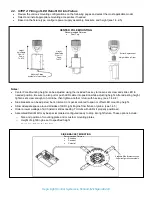
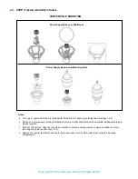
Note:
Screws used to mount LED module and power supply
in fixture are existing screws from previous HID system.
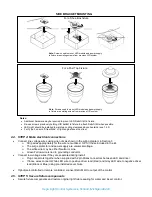
For a Post Top Fixture
SIDE BRACKET MOUNTING
Note:
Screws used to mount LED module and power supply
in fixture are existing screws from previous HID system.
For a Shoe Box fixture


