background image

In Order:

 Number of LBR received in order

Out of Order:

 Number of LBR received out of order

No Match:

 The loopback transaction ID between the LBM and LBR do not match

OAM - Service - LTM

OAM LTM Results

Action: 

RlyHit indicates that the LTM has reached the destination MAC/MEP (i.e., final point)

MAC: 

MAC address of the responder

TTL: 

TTL field on the response, indicated how many hops have been traversed

Flags: 

If set, indicates that only MAC addresses learned in a Bridge's Filtering Database, and not information saved in the MIP

CCM Database, is to be used to determine the Egress Port

Y.1731 Performance Management Functions Results

OAM - Service - LMM

NE=Near End device
FD=Far-End device

OAM LMM Parameters

_e-manual_D07-00-051P_RevD00

Summary of Contents for VePal TX130M+

Page 1: ...TX130M _e manual_D07 00 051P_RevD00...

Page 2: ...e 4 4 2 Ethernet Port 4 4 3 Dual PDH DSn Port 4 4 4 Utility Ports 4 5 LEDs 4 6 Software Upgrade 5 0 Home Menus 5 1 Ethernet and PDH DSn Home Menus 5 2 Action Menu Menu B only 6 0 Menu A Ethernet SyncE...

Page 3: ...FC 2544 Conformance Testing 8 1 RFC 2544 Setup 8 1 1 Header Settings 8 1 2 Frame Settings 8 1 3 Threshold Settings 8 1 4 Throughput Latency Frame Loss and Burst Settings 8 1 5 Control Settings 8 1 6 S...

Page 4: ...ndividual Stream Results 9 2 4 Saving Throughput Multiple Streams Results 10 0 OAM Testing 10 1 OAM Setup 10 1 1 Link Level 802 3ah OAM Setup 10 1 2 Service Level OAM 10 2 OAM Results 10 2 1 Link OAM...

Page 5: ...1588v2 PTP 13 1 Setup 13 1 1 Mode Test Mode 13 2 Test Results 13 3 Protocol Monitor 13 4 1588v2 Wander Measurements 13 4 1 Setup 13 4 2 Results 14 0 Additional Tests Menu A 14 1 NetWiz 14 2 BERT 14 3...

Page 6: ...1 Hierarchy 18 1 2 Interface 18 1 3 Payload 18 1 4 Pattern 18 2 Measurement Configuration 18 2 1 Timer Setup 18 2 2 Performance Analysis 18 2 3 General 18 3 Auto Config 19 0 Results 19 1 PDH Results...

Page 7: ...8 Wander Measurement 21 8 1 Setup 21 8 2 Results 21 9 V 54 22 0 DS1 3 Tools 22 1 DS1 Pulse Mask 22 2 DS1 Loop 22 3 Round Trip Delay 22 4 DS1 Rx Data 22 5 DS3 Pulse Mask 22 6 DS3 FEAC 22 7 DS1 VF 22 8...

Page 8: ...4 4 1 Setup 24 4 2 Results 24 5 1PPS Phase Analysis 24 5 1 Overview 24 5 2 Setup 24 5 3 Results 25 0 MTIE and TDEV Analysis 25 1 Install the MTIE TDEV post analysis software 25 2 Move TIE Data to a PC...

Page 9: ...licensors The purchaser of this device agrees that it has received a license solely to use the software as embedded in the device and the purchaser is prohibited from copying reverse engineering deco...

Page 10: ...n technologies Platform Highlights Intuitive presentation of measurements with test graphics High resolution color touch screen viewable in any lighting conditions fitted with protective cover Robust...

Page 11: ...sure safe operation however please observe all safety markings and instructions Do not operate the instrument in the presence of flammable gases or fumes or any other combustible environment VeEX Inc...

Page 12: ...the memory of the test set If the result is running it will provide a snapshot at the moment the key is pressed The Store function provides automatic storage with automatic naming and timestamping fu...

Page 13: ...d with an intelligent Li ion rechargeable battery pack which is located in the rear of the unit The battery will be partially charged upon delivery so it is recommended to charge the battery fully bef...

Page 14: ...net link with the network and off when there is no link To access the Ethernet management port remove the protective rubber cover on the right hand side of the unit to expose the connector Ethernet ap...

Page 15: ...occurred during the test Red flashing LED Indicates any alarms errors that have occurred Grey LED Indicates that no condition or a test that has not begun yet Note The Signal and Alarm Error lights ar...

Page 16: ...in the FAT 32 file format Verify that the TX130M unit is powered off and that the AC adaptor connected to the unit is charging the battery Insert the USB stick on the right side of the unit Press and...

Page 17: ...Please refer to 7 4 Upgrade section in the ReVeal MTX manual Go back to top Go back to ToC TX130M _e manual_D07 00 051P_RevD00...

Page 18: ...per part of Menu A contains items specific to the test application of the handheld test set while the lower part of the menu contains items common to all VeEX VePAL handheld test sets Menu B features...

Page 19: ...Go back to top Go back to ToC TX130M _e manual_D07 00 051P_RevD00...

Page 20: ...tisements screen Speed Only available when auto negotiation is off Select from 10Mbps or 100Mbps on the 10 100 1000 T port and 100Mbps or 1000Mbps when the 100 1000Base X port is selected Duplex Only...

Page 21: ...R On Off Operation When the 100 1000Base X ports is are selected the top pull down menu appears in the Setup Port screen From this pull down menu the user is able turn the LASER on or off The LASER ma...

Page 22: ...automatically to the application that the profile corresponds to TX130M Profile Selection Viewing a Profile Go back to top Go back to ToC 6 5 Measurement Settings Measurement Tab The measurement and...

Page 23: ...cked Up to 1000 event logs can be stored Circular Only the latest events will be stored if there are over 1000 event logs The oldest event will be deleted so that the new event can be added Blocked On...

Page 24: ...eparate Independent control Start Stop of the transmitter is enabled At the start of the test only the receiver is turned on the user must start the transmitter manually Go back to top Go back to ToC...

Page 25: ...ng at layer 1 2 3 and 4 is supported The test can be configured to use either regular PRBS patterns stress patterns or user defined test patterns to simulate various conditions All patterns are encaps...

Page 26: ...urce MAC address for all streams IP Address A default or user configured IP address is added to the frame This IP address is used as the source IP address for all streams BERT Setup Header Layer 3 Lay...

Page 27: ...aw IEEE 802 3 frame without LLC Not available when Layer 3 is selected Ethernet II DIX named after DEC Intel and Xerox this is the most common frame type today MAC IP Tap the MAC and IP blocks on the...

Page 28: ...otocol Version 6 IPv6 Future Release BERT Setup MAC Address Settings Layer 3 BERT Setup Ethertype Settings Layer 3 Go back to top Go back to ToC VLAN Tab In the VLAN tab the following parameters are c...

Page 29: ...igured in the range 0 to 7 Note This field is three bits in length and maps directly to IP Precedence TOS bits to provide Class of Service COS S bit Can be configured 0 or 1 Note The S field is one bi...

Page 30: ...nt The first six bits of the IP TOS can be edited to provide more granular service classification For more information on the definition of DSCP field in IPv4 and IPv6 headers refer to RFC2474 Time To...

Page 31: ...tter Tolerance Pattern that stresses a receiver by exposing it to extreme phase jumps thereby stressing the Clock Data Recovery CDR circuitry The pattern alternates between repeating low transition de...

Page 32: ...rating at bit rates of 64kbit s and N 64kbit s Fixed All 0s or All 1s User Defined pattern Length depends on size of frame Inversion Normal or inverted BERT Setup PRBS Patterns Go back to top Go back...

Page 33: ...ingle Burst Frame Size Enter the frame size when a Layer 2 or Layer 3 BERT is selected Frame size configuration is not available for Layer 1 BERT Frame sizes can be from 64 bytes to 1518 bytes in addi...

Page 34: ...own menu at the top of the screen Press the Error Injection button to start injecting errors Go back to top Go back to ToC 7 1 4 Control Settings In the Control settings tab the user configures the lo...

Page 35: ...tically discover the far end test unit by pressing the Discover button Once discovered select the remote unit and send a loop up command No manual configuration of the IP address is needed since these...

Page 36: ...BERT Start Go back to top Go back to ToC 7 2 BERT Results 7 2 1 Summary Summary tab The following results including the Start ST and Elapsed ET times are displayed Line rate Mbps Negotiated rate of t...

Page 37: ...ames smaller than 64 bytes containing an invalid FCS Giant frames Number of received frames larger than 1522 bytes containing an invalid FCS BERT Results Summary BERT Results Errors Go back to top Go...

Page 38: ...size distribution Pause frames Frames tab The following Frame distribution statistics are displayed in count and percentage Received RX frames Total frames Test frames VLAN tagged frames VLAN stacked...

Page 39: ...gth field equal to 8808h are counted as pause frames Layer 3 Unicast frames Number of Unicast frames received without FCS errors Layer 3 Broadcast frames Number of Broadcast frames received without FC...

Page 40: ...g bad frames Broadcast frames and Multicast frames Data rate in Mbps Received data rate expressed in Mbps BERT Results Rates Graph BERT Results Rates Details Go back to top Go back to ToC 7 2 7 Delay...

Page 41: ...BERT Results Once the test is completed results can be saved by pressing the save function key on the keypad The results will be saved and named automatically Once saved the user can view or rename th...

Page 42: ...r test The tests are especially popular for the verification of network links with certain service level agreements SLA The following settings must be configured prior to RFC 2544 testing Test layer L...

Page 43: ...Pattern Configurations Tap on the Frame image displayed on the screen to configure the MAC addresses IP addresses VLAN tags MPLS tags and test pattern This brings you to the configuration screens for...

Page 44: ...er fields IP TOS for quality of service testing TTL fragment offset byte and the protocol field Please refer to the BERT application for more details RFC 2544 Header Setups The MAC VLAN MPLS and IP co...

Page 45: ...d when the threshold settings are enabled For example If the throughput threshold value for a 64 byte frame is configured for 80 then a Pass criteria is assigned if the throughput rate is 80 or better...

Page 46: ...ansmit rate will be 90Mbps or 90 of the line rat Resolution 1 to 0 001 The default value is 1 Duration 5 to 999 seconds The default value is 20 seconds The duration is the amount of time the throughpu...

Page 47: ...ine rate or in Mbps For example if the user configures the Max Rate to be 90 and the negotiated line rate of the link is 100Mbps then the maximum transmit rate will be 90Mbps or 90 of the line rate St...

Page 48: ...duration Minimum Duration Selectable in the range 2 to 999 seconds Default value is 2 seconds This is the duration of the first burst Maximum Duration Selectable up to 999 seconds The default value is...

Page 49: ...raffic capacity The two test instruments have to be synchronized because the tests defined in RFC 2544 require the receiver to know the contents of the test signal to be transmitted in detail The TX13...

Page 50: ...op Go back to ToC 8 1 6 Starting Stopping a RFC 2544 Test Once all configurations have been made the user can start the RFC 2544 test The following are three scenarios of how to prepare and start the...

Page 51: ...to the far end unit to remove the loopback that is in place Far End Unit Controlled with Automatic Mode Loop Up Down Commands If the far end unit is not manually looped back then it must first receiv...

Page 52: ...formats Graphical Summary table Test log table RFC Results Throughput Summary RFC Results Throughput Graph RFC Results Throughput Test Log Go back to top Go back to ToC 8 2 3 Latency Latency results a...

Page 53: ...ts Latency Test Log RFC Results Latency Jitter Graph RFC Results Latency Jitter Summary RFC Results Latency Jitter Log Go back to top Go back to ToC 8 2 4 Frame Loss Frame loss results are displayed i...

Page 54: ...Graph Zoomed Go back to top Go back to ToC 8 2 5 Burst Burstability back back results are displayed in the following formats Summary table Test log table RFC Results Burstability Summary RFC Results B...

Page 55: ...sing the save key on the keypad The results will be saved and named automatically Once the results are saved the user may view or rename the results file by going to the Explorer folder located in the...

Page 56: ...he receiver end the traffic is analyzed on a per stream up to 8 streams basis as well as a global or aggregate measurement This application is very useful in verifying the transport of traffic with di...

Page 57: ...an event is logged with corresponding time stamp Total TX Rate This is the total transmit rate configured for all streams If the unit links up to 1Gbps but the total TX rate is configured to 500Mbps...

Page 58: ...tag 2 tags or 3 tags MPLS tag configuration is only available when the MPLS option is purchased MAC VLAN MPLS and IP To configure the MAC addresses VLAN ID priority MPLS label CoS etc IP addresses and...

Page 59: ...b the user is be able to configure the traffic profile per stream including frame size selection traffic type and transmit rate If the same traffic type applies to all streams apply this profile to al...

Page 60: ...or injection can be performed by pressing the Error Inject button on the right side of the screen Error type Select from Bit CRC Bit and CRC OOS IPR TCP UDP Checksum Layer 4 only or Pause Injection Fl...

Page 61: ...ually looped back then it must first receive a loop up command from the control unit before the Throughput test can be started To loop up the far end unit with the manual mode loop up down commands co...

Page 62: ...n of Line Rate For example if we transmit 100Mbps on a 1Gbps interface then the utilization value is 10 or 100Mbps of the total link capacity or Line Rate Total of frames Total number of bad frames Op...

Page 63: ...s Global Aggregate Throughput Results Stream Summary Go back to top Go back to ToC The Global Errors screen displays the Current and Total error count of all streams Bit Indicates errors related to te...

Page 64: ...ck to top Go back to ToC The Global Alarms screen displays the Current and Total alarm count of all streams LOS Loss of Signal LOS Sync Loss synchronization Service disruption associated with loss of...

Page 65: ...ts In the Per Stream tab the following measurements are available Summary Framed rate data rate of bytes total of frames associated with each stream Errors Errors associated with each stream Events Ev...

Page 66: ...Sequence FCS Out of Sequence OOS frames IP Checksum Layer 3 and 4 only Invalid IP Frame Check sequence IP chks Jabber frames Number of received frames larger than 1518 bytes containing an invalid FCS...

Page 67: ...abular and frame size distribution pertaining to each stream Throughput Results Traffic Overview per Stream Throughput Results Frame Types per Stream Throughput Results Frame size per Stream Go back t...

Page 68: ...the save function key on the VePAL keypad If the measurement is not stopped a pop up message will appear warning the user The test results are saved and named automatically Once saved the user may vi...

Page 69: ...Go back to top Go back to ToC TX130M _e manual_D07 00 051P_RevD00...
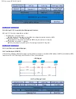
Page 70: ...p Go back to ToC Overview Ethernet OAM provides automatic defect detection fault management and performance monitoring tools for network links and end to end Ethernet Virtual Circuits EVC The OAM serv...

Page 71: ...apabilities configuration and identity to link partners Check on the boxes to advertise selected capabilities during Discovery Remote Loopback Link Event MIB Retrieval Unidirection Go back to top Go b...

Page 72: ...ing capabilities including Frame Loss LM and Delay DM Go back to top Go back to ToC Service Level OAM Configuration Parameters see section 10 3 Definitions for more details Page 1 MD Format Configure...

Page 73: ...is set to MEP this field is ignored Priority 802 1p priority in the LTM LBM VLAN Tag Messages Enter the number of Loopback messages to be sent LBM test only TTL Enter the Time to Live field in the LT...

Page 74: ...Size OAM Link Discovery Page 2 Vendor SPI and OUI Organization Unique identifier and Vendor specific information similar to MAC address fields Discovery State Send Any indicates the device was succes...

Page 75: ...after 5 seconds Unique and Duplicate Events are Threshold crossing events not supported in the current software release Number of Loopback Control frames Variable Request and Response are MIB query me...

Page 76: ...e CCM received could be from another MA UNEXP Unexpected MEP ID or non matching CCM interval Alarm A fault alarm is triggered if a defect is present for a time period of 10s The fault alarm is cleared...

Page 77: ...MEP i e final point MAC MAC address of the responder TTL TTL field on the response indicated how many hops have been traversed Flags If set indicates that only MAC addresses learned in a Bridge s Fil...

Page 78: ...ck to top Go back to ToC 10 3 Definitions 10 3 1 802 3ah OAM Discovery Discovery is the first phase of the 802 3ah protocol During Discovery local and remote units exchange Information OAM PDUs indica...

Page 79: ...ned and operated by a single network provider There is a maintenance level from 0 to 7 to define the hierarchical relationship between domains Maintenance domains can be nested but never intersect MD...

Page 80: ...after no CCM is received for 3 5 times the CCM interval Note There can be 4 094 VLANs per port and up to eight maintenance levels This yields a worst case CCM transmission rate of 9 8 million CCMs pe...

Page 81: ...and MEPs along the path send a response Fault verification and isolation Loopback Verify connectivity to a specific point in the message Equivalent to ping test Go back to top Go back to ToC 10 3 5 Li...

Page 82: ...pback Message LBM LBR LBM Loopback Message are unicast messages transmitted on demand to a destination MAC address A destination address responds with an LBR Loopback Reply Message LBM Diagram Loopbac...

Page 83: ...ers Single Ended Frame Delay Measurement LMM frames contain frame counters Go back to top Go back to ToC 10 3 7 Delay Measurement On demand OAM for measuring Frame Delay FD and Frame Delay Variation F...

Page 84: ...In a Layer 2 or 3 loopback all incoming test traffic will be looped back The loopback function will swap the MAC destination and MAC Source addresses for Layer 2 or MAC and IP destination and source...

Page 85: ...rt Test Port selection Prior to starting the SyncE operation the selected test port must be connected to a network that supports SyncE timing synchronization Port selections include 10 100 1000T and 1...

Page 86: ...Ethernet test port 10 100 1000BaseT or 100 1000BaseX Uses an internal or external reference clock The reference clock used on the SyncE link can be made available for other network elements out of the...

Page 87: ...k source is chosen the external reference clock is connected through the Aux Rx port Clock Source Select between an internal or external clock source Possible external clock sources can be 2 MHz 2 Mbp...

Page 88: ...k measurement function is used for frequency comparison between the SyncE slave recovered clock to a reference source The results are measured in ppm parts per million This function can be used as a q...

Page 89: ...for a file name keep this into account when running time sensitive tests Note Do not remove the USB memory stick while the wander test is running Go back to top Go back to ToC 12 3 2 Results Current T...

Page 90: ...vel of the system clocks located in the network Background or heartbeat is sent once per second as keep alive ESMC information PDU Event message is sent immediately in case the clock quality level has...

Page 91: ...e Length Field QL Quality Level Heirarchy of Quality Levels in Option I of Synchronization Networks Heirarchy of Quality Levels in Option II Synchronization Networks In TX130M the SyncE ESMC SSM optio...

Page 92: ...o back to ToC Setup Mode The TX130M can be set as Master or Slave IPG s Value can be entered by clicking in the box next to it SSM Code Quality Levels Once the parameters are set press Start to start...

Page 93: ...e key to page up or page down End in Pause mode use End key to jump to the end of the trace To view decoded messages press Pause to pause the protocol tracer and tap on the desired message to view dec...

Page 94: ...s file Press Apply to save the file The file is saved under the Files folder on the unit in pcap format The file can be later exported to a PC and analyzed using Wireshark SyncE ESMC SSM Capture SyncE...

Page 95: ...and Subnet All Static fields can be filled by tapping on the section to access an alphanumeric keyboard Local IP IPv4 IPv6 address of the test set Gateway IPv4 IPv6 address of the network gateway CIDR...

Page 96: ...t port 10 100 1000BaseT or 100 1000BaseX The 1588v2 Slave recovered clock can be regenerated out of the PDH TX port with a different clock format and is synchronized Master sync Emulates a 1588v2 Mast...

Page 97: ...lect between Disabled or enter the length of the filter 2 4 6 8 12 The filter is designed to compensate for network jitter by averaging the PTP messages timing values before updating the slave recover...

Page 98: ...itional message information is displayed on the Messages screen The Messages screen gives a further breakdown by message type The total and per second average message rates are displayed Test Results...

Page 99: ...the Delay measurement packet delay variation RTD RTD and Delay Response RTD min and max information The RTD graph measures the time between when the delay_req leaves the slave and the delay_resp is r...

Page 100: ...essage to the master and notes the send time t3 Upon reception of the Delay Request the master notes the time t4 and embeds this information in the Delay Response message 3 The slave is now armed with...

Page 101: ...given to the protocol to provide an accurate and stable recovered clock test signal The Sync PDV graph could be used to establish the level of readiness required for a wander test when the graph has...

Page 102: ...stop if either of the signals used as reference clock or recovered clock test signal have significant levels of impairments are lost or disconnected Press the Stop button to terminate the test If Sav...

Page 103: ...Go back to top Go back to ToC 14 2 BERT Please refer to section 7 0 BERT of this manual Go back to top Go back to ToC 14 3 Scan Please refer to section 17 0 VLAN Scan of this manual Go back to top Go...

Page 104: ...Restart the test Next Profile Move to the next profile in the script for testing This button only appears after the completion of each profile test Cancel Scripting Stops the scripting procedure exit...

Page 105: ...Go back to top Go back to ToC TX130M _e manual_D07 00 051P_RevD00...

Page 106: ...mon to all V100 test sets Please refer to the V100 Common Functions Manual for these sections The sections are renumbered in the V100 Common Functions Manual as follows 14 1 Additional Tests 5 2 Net W...

Page 107: ...iation also known as packet jitter was not included in RFC2544 Jitter is a critical parameter for real time voice and video services It is now part of the SAM test suite RFC2544 validates the service...

Page 108: ...lowed by the FLR and CIR EIR Step 3 Traffic Policing Overshoot Test The purpose of the Traffic Policing Test is to ensure that when transmitting at a rate higher than the allowed CIR EIR the excess tr...

Page 109: ...Test Step Load Test performs only if the Simple Validation test fails Stop test on Fail Enable or Disable Step Tap on the corresponding box to enter the percentage of CIR that the test will reach for...

Page 110: ...and entering a name V SAM Services Header V SAM Services Header Selecting a Stream V SAM Header Configuration Selecting a Stream On the Services tab tap on the stream number S next to the Action Menu...

Page 111: ...r ULR Mbps Select a term to express EIR or select Disable to disable the test Traf Policing Enable or Disable the traffic policing test For this test traffic is transmitted at 25 higher than the CIR E...

Page 112: ...ntrol Settings for information on setting up a remote connection with another unit Note Asymmetric Mode mentioned in that section is unavailable for V SAM Control settings Go back to top Go back to To...

Page 113: ...s for a specific stream CIR test The test passes if all measured values are below the thresholds configured If a threshold is disabled it will not be evaluated towards pass fail criteria CIR EIR test...

Page 114: ...jitter FL Count Counts the number of lost frames FLR Ratio of lost frames to the total transmitted frames AVAIL Minimum percentage of service availability allowed to still be compliant with the SLA Th...

Page 115: ...Go back to top Go back to ToC Events A time stamped record or log of test types and test statuses start stop Events Go back to top Go back to ToC TX130M _e manual_D07 00 051P_RevD00...

Page 116: ...etrics such as frame type rates and errors and alarms VLAN Scan While traffic is being received press Scan The Results tab displays a list of detected VLAN IDs and the percentage of traffic marked wit...

Page 117: ...VLAN IDs from last scan New Profile Creates a new profile Input the number of streams up to 8 Saved Profile Access a saved profile Tap on the magnifying glass next to the stream to configure stream fi...

Page 118: ...r Stream Results tabs please see the Throughput Results section To view measurements for other streams tap on the Stream drop down menu to select a different stream Monitor Setup Viewing Results by St...

Page 119: ...Home Menu To access the Setup application tap on the Setup icon This application allows the user to set up the Transmitter and Receiver interfaces and associated test parameters prior to running a tes...

Page 120: ...ired to be identical or symmetrical coupling the Transmitter and Receiver is possible The signal structure can be copied from Tx to the Rx or vice versa Changes to Setup are applied immediately unless...

Page 121: ...or AMI Normal E1 systems use HDB3 line coding while AMI is reserved for special applications In E3 mode the line code defaults to HDB3 only In DS1 mode the line code options default to B3ZS or AMI In...

Page 122: ...de for a high impedance monitor test or when the receiver is connected directly in parallel to a DS1 line carrying live traffic The isolation circuit of the unit protects the DS1 signal from any possi...

Page 123: ...payloads 1 to 28 channels Fractional DS1 Mux Configures the transmitter for full rate testing at 45Mbit s signal with DS1 payloads 1 to 28 channels for fractional testing using N or M 64kbit s timesl...

Page 124: ...ttern box to access this feature The test patterns can be applied to all PDH DSn rates however ITU T recommends certain sequences dependent on the bit rate under test Coupled Pattern Pattern Use the p...

Page 125: ...Configure a test to run for a fixed duration or a delayed start Mode Manual Timed and Auto selections are available Manual This is linked to the Start Stop function on the pull down menu Timed The te...

Page 126: ...nt bit rate digital paths and connections Long term error performance for Out of Service OOS and In Service Measurement ISM Based on measuring bit errors for connections and block errors for paths Eva...

Page 127: ...ToC 18 3 Auto Config The Auto Configuration function is described below Setup Auto Config The Auto Config function automatically sets the receiver of the TX130M A search of PDH signals at both the el...

Page 128: ...SI standards will be recognized If no test pattern is detected the unit assumes live traffic PDH Signals Unframed or framed payloads at all hierarchies For 2M signals containing 64kbit s timeslots the...

Page 129: ...Alarms The Errors Alarms tab brings up several pages showing the errors and alarm status Page 1 of 4 Dual E1 mode Page 1 of 6 provides an overview of all the errors and alarms applicable to the signa...

Page 130: ...that are associated with the signal under test All alarms are evaluated and stored The time resolution of alarms is 100ms Errors Alarms Tab Page 2 Errors Alarms Tab Page 4 Dual E1 Mode Go back to top...

Page 131: ...rror and alarm events recorded during a test The events are presented in chronological sequence Number Event number events are numbered sequentially Type Indicates alarm or error type Start Indicates...

Page 132: ...standard rate and the rate of the input signal Min ppm Indicates the difference between the standard rate and the minimum deviation detected in the input signal Max ppm Indicates the difference betwee...

Page 133: ...lies to the installation and maintenance of the network and defines Bringing Into Service BIS procedures and test limits for fault detection and localization The ITU T recommendations are described in...

Page 134: ...s when the event occurred since the test was started The upper left and right arrows allow the user to scroll through the measurement period while the and keys allow zooming of the time axis The event...

Page 135: ...back to ToC 19 1 7 Graph The Bar tab brings up the screen displaying a log of the Errors recorded during the measurement interval A dedicated page is available for each error type Scroll through the...

Page 136: ...the user to scroll through the measurement period while the and keys allow zooming of the time axis A View status screen can be accessed by tapping on the result area A start and finish time includin...

Page 137: ...nals LOS LOF AIS RDI DS1 signals AIS Yellow idle LOS LOF DS3 signals LOS LOF OOF AIS Parity Alarm Flow Continuous Count Alarm Duration 0 1s 1s 10s 100s Error Type E1 signals Code FAS CRC REI E bit Bit...

Page 138: ...l down menu At any time during the test process you can inject errors or generate alarms by tapping the Error Injection and Alarm Generation buttons in the pull down menu Alarm Error Injection Menu Go...

Page 139: ...portion of the pulse will be reflected when and wherever it encounters an impedance mismatch The reflection is proportional to the impedance mismatch i e the greater the mismatch the greater the refle...

Page 140: ...The TX130M should be connected to transmission system to ensure that the switching time is measured for the service transported by the E1 links 2 Ensure that no errors or alarms are present on the tr...

Page 141: ...vent simulation of FAS Bit 3 A shows the remote alarm indication Bits 4 to 8 Sa4 to Sa8 are spare bits often used for SSM QL Tx Bits Sa4 to Sa8 are used to send optional network messages The Sa bits s...

Page 142: ...ooped back signal Set check box on Setup Rx pattern to Out of Service Go back to top Go back to ToC 21 5 E1 Rx Data Tapping the E1 Rx Data the E1 Tools screen displays the PDH E1 Rx Data showing recei...

Page 143: ...transmit signal Transmit audio data from the external headset into selected timeslot Code Options u Law or A Law Programmable ABCD Manual edit ABCD User or IDLE SEIZE Transmitted Frequency Options 50...

Page 144: ...IE measurements on screen only ON sends real time TIE measurements to an attached USB memory for further post analysis refer to the MTIE and TDEV Analysis section This feature requires the MTIE and TD...

Page 145: ...ks analysis refer to the MTIE and TDEV Analysis section Both Wander Analysis and MTIE TDEV Post Analysis are optional features PDH Wander Measurements Menu Go back to top Go back to ToC 21 9 V 54 The...

Page 146: ...s cannot be detected by the receiver correctly bit and code errors will result The pulse amplitude and overall shape are superimposed and compared with the Telcordia TR TSY 000499 and ITU T G 703 puls...

Page 147: ...eclare pre exist loop and stop 2 Send the loop up code for 5 seconds If in band check if the loop up code is returned If out of band ESF FDL send a known pattern in the payload and check if the known...

Page 148: ...hows received data and captures the current timeslots DS1 Rx Data Go back to top Go back to ToC 22 5 DS3 Pulse Mask This function captures and analyzes DS3 44 736Mbits s pulse shape The purpose of mai...

Page 149: ...send and receive loop up codes and information from the far end T3 device You can enable and disable through a drop down menu in this field LoopUP Activate 00010010 11111111 sent 10 repetitions LoopDo...

Page 150: ...SINGLE DS1 LOS DS1 EQUIP FAIL NON SERVICE AFFECT LOOP TYPE Options NIU LINE DS3 FEAC Tasks Page 1 DS3 FEAC Tasks Page 2 Go back to top Go back to ToC 22 7 DS1 VF Tapping the VF the DS1 Tools screen di...

Page 151: ...n the transmit signal Transmit audio data from the external headset into selected timeslot Code Options u Law or A Law Programmable ABCD state for On Hook Off Hook Wink User Transmitted Frequency Opti...

Page 152: ...grid spacing is 2 0UIpp Red Bar is Max peaked jitter during testing and Yellow is the current peaked jitter Press Start to start measurement Select the HP1 LP 10Hz to 40kHz or HP2 LP 8kHz to 40kHz fi...

Page 153: ...folder structure Profile Menu To save a new profile from the PDH DS1 3 applications mentioned above select the Save as New pull down menu option This will bring up an alpha numeric keypad to name the...

Page 154: ...Mode TE or NT TE Terminating Equipment used when the TX130M is emulating customer equipment TE usually uses the received signal to clock the transmitter NT Network Terminal is used when the TX130M is...

Page 155: ...Automatically answers incoming calls Cancel Automatically rejects incoming calls Sub Addr Type NSAP or User My sub Tap on the box and enter the sub address number using the alphanumeric keyboard Codec...

Page 156: ...2D or 47B D in T1 mode or Dual PRI in E1 the user can choose which line to use Numbering Type Unknown International National or Local Numbering Plan Unknown Telephony or Private Dial To Tap on the cor...

Page 157: ...establishment layer 3 decodes allow technicians to verify such factors as call state who made or dropped the call why the call was dropped where the call is being carried Interface ID B channel and ca...

Page 158: ...BER measurements When viewing BER measurements verify that both the PAT SYNC LED and the appropriate framing LED are green These two LEDs signify that the patterns and framing match for the transmitt...

Page 159: ...rect Dialing In adds a number of telephone number to a circuit which can be used to dial that BRI common use is a company number with individual 4 or 4 digit extension numbers that can be dialed HOLD...

Page 160: ...Multi Call by Single Call Number Multi Call Map L1 Multi Call Result ISDN Phone Number List Using Reveal MTX TX130M _e manual_D07 00 051P_RevD00...

Page 161: ...es access the DTMF tab An alphanumeric keypad will be displayed DTMF tones are transmitted as soon as they are typed DTMF Go back to top Go back to ToC 24 1 9 DBackup To setup a backup D Channel go to...

Page 162: ...1 2 Signal BMap Line Detects active traffic on the timeslots The user can listen to the conversation by pressing on active call cells Please see 24 1 7 Multi Call for more information Trace Please se...

Page 163: ...ppropriate test port type to match the balanced or unbalanced and impedance characteristics of the signal under test Ref Clk Port Select the appropriate connector or port required to match reference c...

Page 164: ...uter and open it with the VeEX Wander Analysis PC software for further MTIE TDEV and masks analysis refer to the MTIE and TDEV Analysis section Both Wander Analysis and MTIE TDEV Post Analysis are opt...

Page 165: ...also used to adjust GPS receivers to compensate for physical delays Go back to top Go back to ToC 24 5 2 Setup 1PPS Phase Analysis compares the phase difference between two 1PPS Clocks Resolution is 1...

Page 166: ...compared to the 1PPS reference for the last 200 seconds for a quick visual verification of accuracy and stability Vertical Scales 1 s 10 s 100 s 500 s Horizontal Scale 200s 50s div 1PPS Phase Analysi...

Page 167: ...Go back to top Go back to ToC 25 1 Install the MTIE TDEV post analysis software Copy the VeEX_Wander_Analysis zip package to a PC or USB drive Unzip the folder and move it to the desired destination C...

Page 168: ...op Go back to ToC 25 4 MTIE TDEV Masks VeEX s Wander Analysis PC tool includes the most common wander masks After the MTIE and TDEV Analysis is done select the masks that fit the requirements Selected...

Page 169: ...red masks are not listed new ones can be added MTIE and TDEV masks are defined in plain text and with a simple notation 1 Open the Wander Analysis folder and go to User Mask 2 Select a similar mask to...

Page 170: ...Use and to define the ranges Starts the TDEV definition section Use a comma to separate range from mask values Use spaces between formula elements Write negative exponentials in parenthesis x 0 5 for...

Page 171: ...Go back to top Go back to ToC TX130M _e manual_D07 00 051P_RevD00...

Page 172: ...of of purchase within thirty 30 days of the request by the customer freight prepaid Additionally during the warranty period VeEX Inc will provide without charge to the customer all fixes patches and e...

Page 173: ...ailable in pdf format by clicking the link or specification sheet below Please note you will need Adobe Reader version 9 0 or higher to open and view the file To get the latest free version of Adobe R...

Page 174: ...opy of the CE Declaration of Conformity relating to VeEX products please contact VeEX customer service What is RoHS RoHS is the acronym for Restriction of Hazardous Substances Also known as Directive...

Page 175: ...ibution channel provides uncompromised product and technical support Visit us online at www veexinc com for latest updates and additional documentation Corporate Headquarters VeEX Incorporated 2827 La...

Reviews: