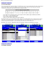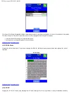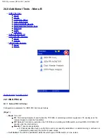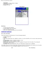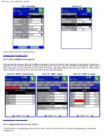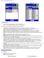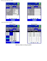
The Jitter Measurement submenu allows the user to measure and analyze received signal jitter. The measurements example is
shown above (the vertical grid spacing is 2.0UIpp). Red Bar is Max. peaked jitter during testing and Yellow is the current peaked
jitter.
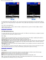
Press "Start" to start measurement.
Select the HP1+LP (10Hz to 40kHz) or HP2+LP (8kHz to 40kHz) filter for DS1, and HP1+LP (10Hz to 400kHz) or HP2+LP
(30kHz to 400kHz) filter for DS3.
_e-manual_D07-00-051P_RevD00
Summary of Contents for VePal TX130M+
Page 1: ...TX130M _e manual_D07 00 051P_RevD00...
Page 19: ...Go back to top Go back to ToC TX130M _e manual_D07 00 051P_RevD00...
Page 69: ...Go back to top Go back to ToC TX130M _e manual_D07 00 051P_RevD00...
Page 105: ...Go back to top Go back to ToC TX130M _e manual_D07 00 051P_RevD00...
Page 171: ...Go back to top Go back to ToC TX130M _e manual_D07 00 051P_RevD00...


