
Mag Probe Installation
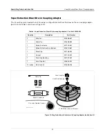
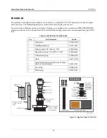
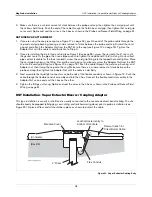
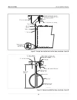
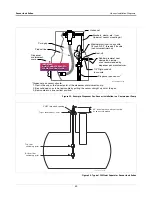
UST Installation - Vapor Extractor Riser w/ Coupling Adaptor
29
1.
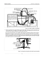
Remove any existing hardware from the Vapor Extractor Riser so that it’s 4” NPT riser threads are exposed.
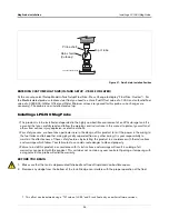
2. Use the extractor wrench tool (OPW Part Number: 89-0044) to remove the Ball Float Check Valve and
Extractor Cage inside the bottom of the 4” riser (ref. Figure 10 on page 18). Important! - Ball Float Check
Valve and Extractor Cage may be difficult to remove;
use caution
.
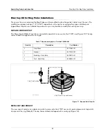
3. Remove any sludge from the bottom of the tank.
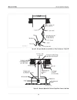
4. Assemble the probe floats, spacer rings, and cable as per the Mag Probe Assembly Manual.
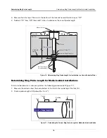
5. Gently slide the float(s) to the bottom of the probe shaft. Important! - Handle probes carefully. Striking or
dropping the probe will result in loss of calibration and could cause permanent damage.
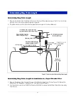
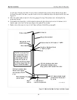
6. Carefully lower the probe into the riser pipe until the boot rests on the bottom of the tank.
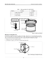
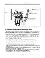
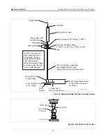
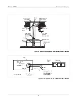
7. Thread the probe cable through the bottom of the new Coupling Adaptor and out the tapped opening in its
side.
8. Screw the Coupling Adaptor onto the 4” riser until the gasket first contacts the riser pipe. Then use a pipe
wrench to tighten the Coupling Adaptor an additional 3/4 turn.
9. Test pull the cable to insure that it is free of spring and that the probe is resting on the bottom of the tank.
(Make sure there is some slack in the cable.)
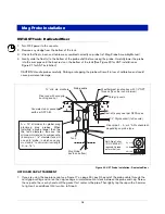
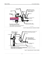
10. Slip the PG7 cord grip fitting (“0” ring end first) over the cable and screw it into the tapped hole in the
Coupling Adaptor (ref Figure 13 on page 20 for the correct PG7 cord grip assembly). Tighten snugly -
Be
careful not to overtighten.
Slide the domed nut of the PG7 fitting down the cable and tighten securely onto
the PG7 fitting so that the cable stays firmly in place.
Again, be careful not to overtighten.
11. Reattach the riser cap from the original installation onto the Coupling Adaptor.
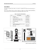
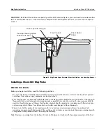
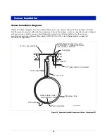
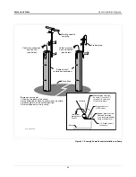
12. Position the Shield-Fitting over the PG7 cord grip and secure with the hose clamp (see Figure 24 on
13. Splice the probe cable to the direct burial cable as shown in the Probe and Sensor Field Wiring on page 51,
and seal following instructions shipped with the splice kit. Observe polarity!
14. Secure splice enclosure against the Shield-Fitting with the tie wrap.
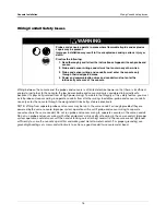
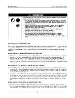
CAUTION:
If Ball Float Check Valve was part of your Overfill Protection System, you now need to consider another
form of overfill protection (i.e. TLS alarm or drop tube with overfill protection valve or some other accepted means).


