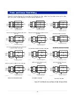
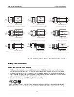
Sensor Installation
Sensor Installation Diagrams
39
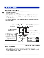
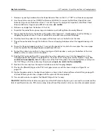
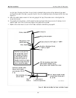
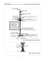
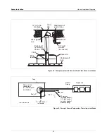
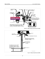
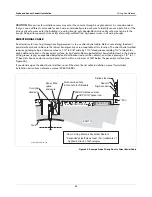
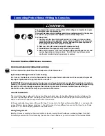
Figure 31. Example Interstitial Position Sensitive Sensor Installation - Steel UST
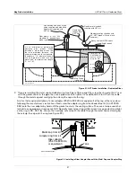
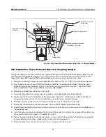
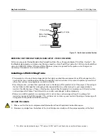
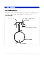
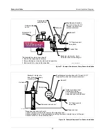
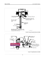
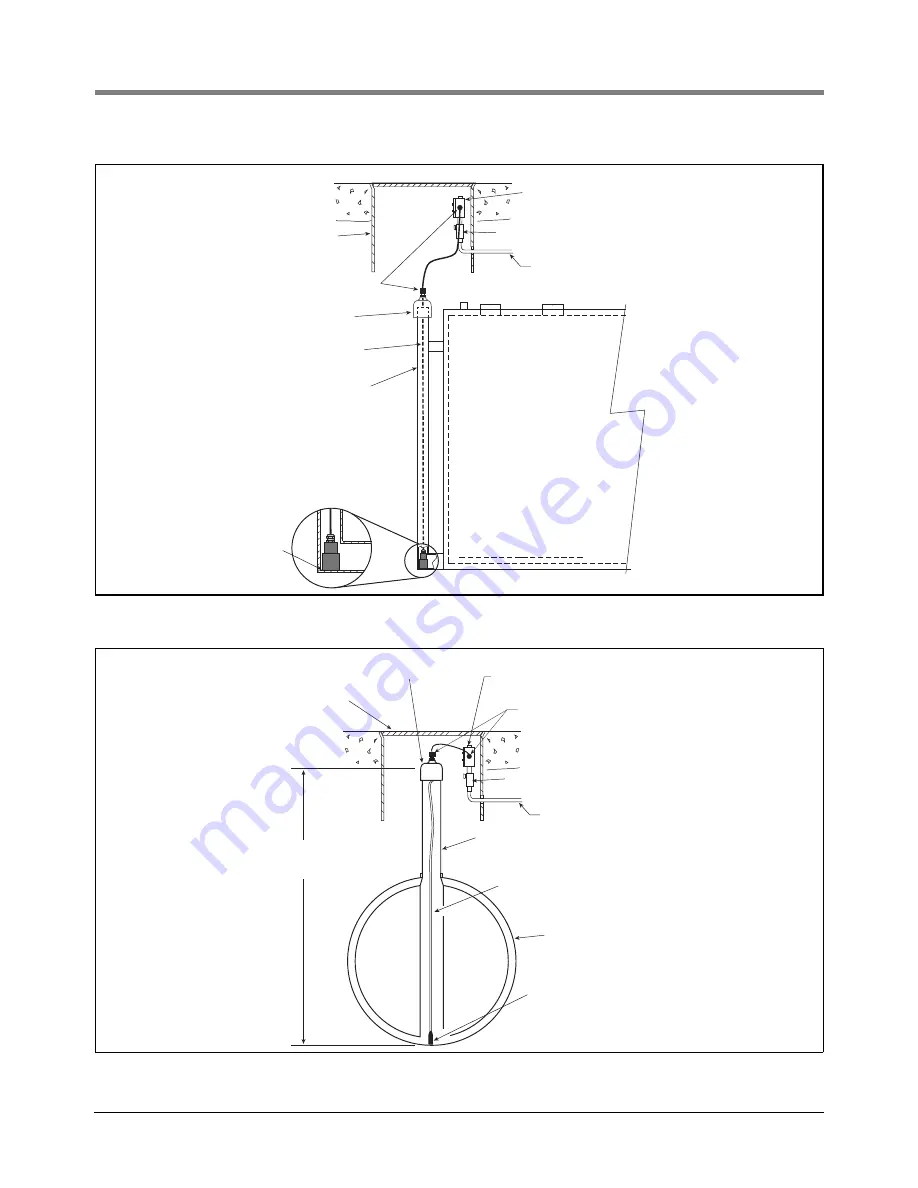
Figure 32. Example Interstitial MicroSensor Installation - Steel UST
2'' dia. riser
Leader cable
1/2" to 2"
Reducer
Weatherproof junction box with
1/2-inch N.P.T. threads (16 Cubic
inch volume minimum)
14'' min. dia. manhole
1/2'' rigid conduit (to Console)
.
.
.
.
.
.
.
.
.
.
.
.
.
.
.
.
.
.
.
.
.
.
.
.
.
.
.
.
Seal-off
Cord grips
S
en
s
or m
us
t re
s
t
on
b
ottom of
inter
s
titi
a
l ri
s
er
Minimum riser
diameter 1 inch
sensors\micrinst.eps
Sensor must rest
on bottom of tank
Sensor cable
1/2'' to X'' reducer
(x = riser diameter)
Steel tank
Distance to
measure
Weatherproof junction box with
1/2-inch N.P.T. threads (16 Cubic
inch volume minimum)
14'' min. dia. manhole
1/2'' rigid conduit (to Console)
.
.
.
.
.
.
.
.
.
.
.
.
.
.
.
.
.
.
.
.
.
.
.
.
.
.
.
.
Seal-off
Cord grips