VN-200 User Manual
UM004
www.vectornav.com
35/47
5.11
Communication Protocol Control
Communication Protocol Control
Register ID :
30
Firmware :
v0.1 and up
Access :
Read / Write
Comment :
Contains parameters that control settings relating to the communication protocol
used to communicate with the VN-200.
Size (Bytes):
7
Example Serial Read Register
Response:
$VNRRG,30,2,0,0,0,1,0,1*6E
Byte
Offset Name
Number
Format
Unit Description
0
SerialCount
U1
-
Provides the ability to append a counter to the end of the serial
asynchronous messages.
1
SerialStatus
U1
-
Provides the ability to append the status to the end of the serial
asynchronous messages.
2
SPICount
U1
-
Provides the ability to append a counter to the end of the SPI
packets.
3
SPIStatus
U1
-
Provides the ability to append the status to the end of the SPI
packets.
4
SerialChecksum
U1
-
Choose the type of checksum used for serial communications.
5
SPIChecksum
U1
-
Choose the type of checksum used for the SPI communications.
6
ErrorMode
U1
-
Choose the action taken when errors are generated.
5.11.1
SerialCount
The SerialCount field provides a means of appending a time or counter to the end of all asynchronous
communication messages transmitted on the serial interface. The values for each of these counters
come directly from the Synchronization Status Register.
With the SerialCount field set to OFF, a typical serial asynchronous message would appear as the
following:
$VNYPR,+010.071,+000.278,-002.026*60
With the SerialCount field set to one of the non-zero values, the same asynchronous message would
appear instead as:
$VNYPR,+010.071,+000.278,-002.026,T1162704*2F
When the SerialCount field is enabled, the counter will always be appended to the end of the message
just prior to the checksum. The counter will be preceded by the T character to distinguish it from the
status field.
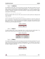
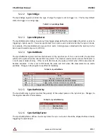
Table 25 – SerialCount Field
Mode
Value
Description
NONE
0
OFF
SYNCIN_COUNT
1
SyncIn Counter
SYNCIN_TIME
2
SyncIn Time
SYNCOUT_COUNT
3
SyncOut Counter


