VN-200 User Manual
UM004
www.vectornav.com
24/47
5
System Registers
The VN-200 module contains a collection of registers used for configuring the module and accessing the
data it produces. These registers may be read or written to using the Read Register and Write Register
commands (Sections 4.4.1 and 4.4.2). When the module is rebooted or power-cycled, values written to
the registers will revert back to their previous values unless a Write Settings command has been issued
(Section 4.4.3) to save the registers to non-volatile memory.
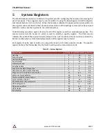
Table 21 below provides a quick reference for all of the registers and their associated properties. The
second column lists the Access ID, which is used to identify a specific register. The third column
indicates the width of the register in bytes (relevant only in SPI mode) and the last column provides the
Section number where a more detailed explanation of the register may be found.
Each register may be read or written to using either serial or SPI communication modes. The specific
register Sections that follow describe the format used by each communication mode.
Table 21 –System Registers
Register Name
Access ID
Width (bytes)
Section
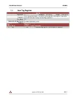
User Tag
0
20
5.1
Model Number
1
24
5.2
Hardware Revision
2
4
5.3
Serial Number
3
12
5.4
Firmware Version
4
4
5.5
Serial Baud Rate
5
4
5.6
Asynchronous Data Output Type
6
4
5.7
Asynchronous Data Output Frequency
7
4
5.8
Magnetic and Gravity Reference Vectors
21
6 x 4
5.9
Reference Frame Rotation
26
9 x 4
5.10
Communication Protocol Control
30
7
5.11
Synchronization Control
32
20
5.12
Calibrated Sensor Measurements
54
11 x 4
5.13
GPS Configuration
55
4
5.14
GPS Antenna Offset
57
3 x 4
0
GPS Solution
58
68
5.16
INS Solution
63
72
5.17


