background image

45

46

Summary

Note 3: Motor start fuses or thermal circuit breakers are recommended for this application.
             Check local requirements for your situation in this regard.

Due to variations that can occur in manufactured products, claimed performance, voltages,
ratings, all capacities, measurements, dimensions and weights quoted are approximate 
only. Achievable capacities and ratings in use and operation will depend upon correct 
installation, use, applications, maintenance and service.

2.5 Duty Cycle

       The rated duty cycle of a Welding Power Source, is a statement of the time it may be 

operated at its rated welding current output without exceeding the temperature limits of 
the insulation of the component parts. To explain the 10 minute duty cycle period the 
following example is used. Suppose a Welding Power Source is designed to operate at
a 40% duty cycle, 200 amperes at 18 volts. This means that it has been designed and
built to provide the rated amperage (200A) for 5 minutes, i.e. arc welding time, out of 
every 10 minute period (40% of 10 minutes is 5 minutes). During the other 5 minutes of
the 10 minute period the Welding Power Source must idle and be allowed to cool. The 
thermal cut out will operate if the duty cycle is exceeded.

D

u

ty C

y

c

le

(P

E

R

C

E

N

T

A

G

E

)

Welding Current(AMPS)


2m Power cable 

200 Amp Electrode Holder With 3m 

300 Amp Earth Clamp With 3m 


TIG Torch WP-17 4m

1.8m Gas Hose

Operating Manual 

2.6  Packaged Items

25

25

50

50

75

75

100

100

1

25

1

25

150

150

175

175

0

0

10

10

20

20

30

30

40

40

50

50

60

60

70

70

80

80

90

90

100

100

2

0

0

225

250

275

275

0

0

Safe Operating Region
            (TIG&MMA)

300

M

MA

TIG

AC/DC WIG SERIES EQUIPMENT

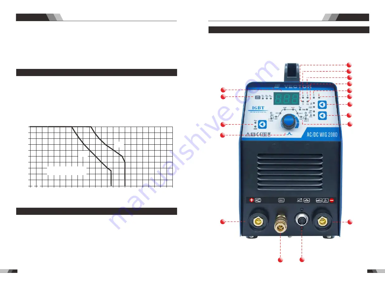
3.1 Layout For The Panel 

Front

Operation

AC/DC WIG SERIES EQUIPMENT

10

9

9

2

4

11

12

13

9

4

8

7

6

5

9

1

3

15

9

14

16

17

Summary of Contents for AC/DC WIG 200D

Page 1: ...ING TECHNOLOGY GmbH Ihr Partner für Schweißtechnik Your Partner For Welding Technology AC DC WIG 200D Register now and benefit Jetzt Registrieren und Profitieren VECTOR WELDING TECHNOLOGY GmbH 2Years 5Years transformer and rectifier www vector welding com ...

Page 2: ... 40 1 2 Effects of low frequency electric and magnetic fields 40 40 1 3 Symbol chart 41 41 1 Safety instructions 5 Troubleshooting 5 1 Troubleshooting 61 63 4 Welding technique 4 1 TIG Basic Welding Technique 56 56 4 2 Joint froms in TIG 56 56 4 3 The explanation of welding quality 57 57 4 4 TIG Parameters Matching 57 59 4 5 MMA Basic Welding Technique 59 60 6 Maintenance 6 1 Maintenance 64 64 2 S...

Page 3: ...eißtechnik Lieferanten entdecken Sie die Möglichkeiten profitieren Sie von dem Angebot moderne und qualitativ hochwertige Schweißausrüstung zu einem unschlagbaren Preis Nummer 1 in der Technik Nummer 1 bei den Preisen Nummer 1 im Service Nummer 1 in der Umweltverträglichkeit Aufgrund von 4 strategischen Zielen arbeitet unsere Firma jeden Tag an der Optim ierung diese Vision Mehr als 30 000 begeist...

Page 4: ...ARBEITEN NUR VON SACHKUNDIGEN PERSONEN TÄTIGEN Die Sicherheitsübungen sind nach dem Europäischen StandardEN60974 1konzipiert 4 Trennen Sie die Eingangsleistung oder stoppen Sie die Maschine bevor Sie das Gerät einrichten oder benutzen Der Hauptschalter gegen Wiedereinschalten ist mit einem Schloss zu sperren und die Netzsicherungen zu entfernen sodass der Strom nicht verse hentlich eingeschaltet w...

Page 5: ...bogen Sollte dies nicht möglich sein decken Sie die Materialien fest mit einer vorgesehenen Abdeckung ab 1 Schützen Sie sich und andere von fliegenden Funken und heißem Metall 4 Rechnen Sie damit dass Schweißfunken und heißes Material einfach durch kleine Risse und Öffnungen zu benachbarten Bereichen vordringen kann 5 Beachten Sie die Brandgefahr und halten Sie einen Feuerlöscher in der Nähe 6 Das...

Page 6: ...n beinhalten Säuren und erzeugen explosive Gase 1 Bei der Arbeit an Batterien immer einen Gesichtsschutz tragen 2 Den Motor vor dem Trennen oder Anschließen der Batterien abschalten 3 Beim Arbeiten mit der Batterie keine Arbeitsgeräte verwenden die Funkenflug verursachen 4 Benutzen Sie kein Schweißgerät um Batterien zu laden oder Autos Starthilfe zu geben WARNUNG DAMPF UND HEISSEM UNTER DRUCK STEH...

Page 7: ...requenz und Hochspannung für die Lichtbogenzündung um den Erfolg der entzündeten Lichtbogen zu gewährleisten sorgt für die Verpolungszündung für ein gutes Zündverhalten beim TIG AC Schweißen Vermeiden des Wechselstrom Lichtbogenbrüches mit speziellen Mitteln auch wenn Lichtbogenbruch auftritt hält die HF den Lichtbogen stabil Pedal steuert den Schweißstrom TIG DC Betrieb wenn die Wolfram Elektrode...

Page 8: ... dem herkömmlichen Sch 2 weißstrom I ist dargestellt 2 Relation zwischen herkömmlicher Ladungsspannung und Schweißstromstärke Volt Ampere Charakteristik Arbeitspunkt 2 4 Spezifikationen 170A 25 26 8V 85A 100 23 4V 200A 40 18V 126A 100 15V 8 7 kg 10 170A 10 200A 15 4A 30 9A 10KVA H425mmxB152mmxT291mm Bezeichnung Gewicht der Schweißgeräts Abmessungen des Schweißgeräts Kühlung Schweißmaschinentyp Eur...

Page 9: ...istung betrieben werden kann ohne die Temperaturgrenzen der Isolierung der Bauteile zu überschreiten Um die 10 Minuten Einschaltdauer zu erklären wird folgendes Beispiel verwendet Man nehme an dass eine Schweißstromquelle so ausgelegt ist dass sie bei einem Arbeitszyklus von 40 arbeitet das sind 200 Ampere bei 18 Volt Dies bedeutet dass sie so konstruiert und gebaut wurde dass sie die Nennstromstä...

Page 10: ...sbare Arc Force Korrektur Anti Stick verhindert dass die Elektrode glühen Sollte die Elektrode trotz der Arc Force Vorrichtung kleben gibt die Anlage innerhalb von 1 Sekunde den eingestellten Maximalstrom ab was das Festkleben und Überhitzen der Elektrode verhindert Dadurch können Elektrode und Elektrodenhalter einfach von dem Schweißgerät entfernt werden Antistick Antistick U I 3 Mode Knopf Drück...

Page 11: ...ßstromabgabe wird dabei nicht unterbrochen Zum Deaktivieren der Schweißstromquelle muss der Brennerschalter erneut gedrückt und freigegeben werden Auf diese Weise muss der Schweißer den Brennerschalter nicht ständig gedrückt halten Hinweis Beachten Sie dass die Stromquelle beim TIG Schweißen HF TIG Schweißen und TIG Abstandsschweißen solange aktiviert bleibt bis die ausgewählte Stromabfallphase ab...

Page 12: ...AC Frequenz bietet einen stärker fokussierten Bogen mit erhöhter Richtungssteuerung Hinweis Verringerung der AC Frequenz Erweicht den Lichtbogen und erweitert die Schweißpfütze für eine breitere Schweißnaht Breitere Schweißraupe gute Eindringtiefe ideal für Aufbau Arbeiten Schmalere Schweißraupe für Kehlnähte und automatisierte Anwendungen 4 Maximalstromstärke Verstell Bereich 10 200 AMP DC TIG un...

Page 13: ...raupe Keine sichtbare Reinigung Breitere Schweißraupe und Reinigung Schmalere Schweißraupe ohne sichtbare Reinigung 10 Wellenausgleich Einstellbar zwischen 10 30 Breitere Schweißraupe und Reinigung Schmalere Schweißraupe und Reinigunsghandlung Dieser Parameter ist nur in den AC TIG Schweißmodi mit Wechselstrom aktiv und wird dafür verwendet das Verha ltnis zwischen Eindringtiefe und Reinigungswirk...

Page 14: ...chten 10 Stellen Sie den Schweißvorgang auf LIFT TIG ein 11 Stellen Sie den Schweißstromregler auf die gewünschte Stromstärke ein 12 Jetzt können Sie mit dem LIFT TIG Schweißen beginnen Inbetriebnahme AC DC SERIENAUSRÜSTUNG AC DC SERIENAUSRÜSTUNG Der Inhalt an Staub Säuren korrosive Gase in der Umgebungsluft oder Substanz Achten Sie darauf dass es eine ausreichende Belüftung während des Schweißen ...

Page 15: ... Schweiß bereiches Helles Silber Orange Gelb Blau Violett Grün Weißes Titanoxid Pulver 4 4 Anpassung der Parameter beim TIG Schweißen Die Beziehung zwischen Gasdrüsendurchmesser und Elektrodendurchmesser Gasdrüsendurchmesser 6 4mm 8mm 9 5mm 11 1mm Gasdrüsendurchmesser 0 5mm 1 0mm 1 6 or 2 4mm 3 2mm Hinweis Die oben genannten Parameter wurden dem Welding Dictionary S 142 Volume 1 von Edition 2 entn...

Page 16: ...n 25cm min 30cm min 25cm min 25cm min 20cm min 25cm min Hinweis Die oben genannten Parameter wurden dem Welding Dictionary S 150 Volume 1 von Edition 2 entnommen Parameter beim AC TIG MMA Schweißen für Aluminium und Legierungen Dicke Durchmes ser des Schweiß drahtes Durchmes ser der Wolfram Elektrode Schweiß stromstärke Flussrate des Argon Gases Durchmes ser der Gas Drüse Hinweis 1 6mm 1 6 2 0mm 2...

Page 17: ...e einen Stromschlag zu bekommen Schweißverfahren AC DC SERIENAUSRÜSTUNG 5 1 Grundlegende Fehlerbehebung Bevor Sie die an die Maschine gebundene Kabel rausziehen vergewissern Sie sich dass die Lichtbogenschweißmaschine ausgeschaltet ist Wenn irgendein Problem entsteht und kein Fachpersonal vor Ort ist wenden Sie sich bitte an die lokalen Fachleute oder Zweigniederlassung Nur fachgerechte Wartungspe...

Page 18: ...ie AC Antriebsplatte ist beschädigt Reparieren oder wechseln Sie es Ersetzen Sie sie Trennen Sie die Stromversorgung beim Wechseln des Schweißbrenners Das AC IGBT IGBT Modul ist beschädigt Ersetzen Sie es Steuertafel ist defekt Reparieren Sie sie oder tauschen Sie sie aus AC DC SERIENAUSRÜSTUNG AC DC SERIENAUSRÜSTUNG Warnung für die SicherheitunterBeibehaltung der Maschine schaltenSiebitte die Ver...

Page 19: ...ollte etwas die Lüfter Flügel blockieren entfernen Sie den Störfaktor Sollte die Lüftung nach Entfernen des Störfaktors immer noch nicht rotieren drehen Sie die Flügel vorsichtig in Richtung der Lüftung Sollte die Lüftung danach normal rotieren muss die Startkapazität zurückgesetzt werden Ist dies nicht der Fall sollte die ganze Lüftung ersetzt werden Überprüfen Sie ob der Schnell Anschlusslose un...

Page 20: ...ze this vision Number 1 in Technology Number 1 in the prices Number 1 in Service Number 1 in the environmental compatibility More than 30 000 enthusiastic customers trust our equipment in the welding and plasma technology They confirm the success of these trendsetting strategy In addition to the stringent quality test and the test in the production we subject the equipment a thorough inspection be...

Page 21: ...m the welding process produce intense heat and strong ultraviolet rays that can burn eyes and skin Noise from some processes can damage hearing 1 Wear a welding helmet fitted with a proper shade of filter to protect your face and eyes when welding or watching 2 Wear approved safety glasses Side shields recommended 3 Use protective screens or barriers to protect others from flash and glare warn oth...

Page 22: ...trode from holder or cut off welding wire at contact tip when not in use Safety instructions AC DC WIG SERIES EQUIPMENT AC DC WIG SERIES EQUIPMENT WARNING SPARKS can cause battery gases to explode BATTERYACID can burn eyes and skin Batteries contain acid and generate explosive gases 1 Always wear a face shield when working on a battery 2 Stop engine before disconnecting or connecting battery cable...

Page 23: ...ing to ensure the success ratio of igniting arc the reverse polarity ignition ensures good ignition behavior in TIG AC welding Avoid AC arc break with special means even if arc break occurs the HF will keep the arc stable Pedal control the welding current In DC TIG without HFopertation If the tungsten electrode touches the workpiece when welding the current will drop to short circuit current to pr...

Page 24: ...nto DC about 312 V then is conv erted to medium frequency AC about 20 40KHz by inverter device IGBT module after reducing voltage by medium transformer the main transformer and rectifying by medium fre quency rectifier fast recovery diodes then is outputted DC or AC by selecting IGBT module The circuit adopts current feedback control technology to insure current output stably Meanwhile the welding...

Page 25: ...used Suppose a Welding Power Source is designed to operate at a 40 duty cycle 200 amperes at 18 volts This means that it has been designed and built to provide the rated amperage 200A for 5 minutes i e arc welding time out of every 10 minute period 40 of 10 minutes is 5 minutes During the other 5 minutes of the 10 minute period the Welding Power Source must idle and be allowed to cool The thermal ...

Page 26: ...lectrode types at low current strengths with a short arc in particular I t Anti stick prevents the electrode from annealing If the electrode sticks in spite of the arcrorce device the machine automatically switches over to the minimum current within about 1 second to prevent the electrode from overheating In order to easily separate the electrode and electrode holder to protect the welder Antistic...

Page 27: ...to operate thus allowing the unit to cool sufficiently Do not switch the unit off should a thermal overload condition be present 9 Power ON Indicator The POWER ON indicator illuminates when the ON OFF switch is in the ON position and the correct mains voltage is present 12 Process Selection Button The process selection control is used to select the desired welding mode Two modes are available GTAW...

Page 28: ...ontrol Note Decreasing the AC Frequency softens the arc and broadens the weld puddle for a wider weld bead 9 AC Frequency Setting ranges 50HZ 200HZ This parameter operates in AC TIG mode only and is used to set the frequency for the AC weld current 10 Wave Balance Setting arranges 10 30 This parameter operates in AC TIG mode and is used to set the penetration to cleaning action ratio for the AC we...

Page 29: ...al however that the male plug is inserted and turned securely to achieve a sound electrical connection Select STICK mode with the process selection control a n d co n n e ct th e w o rk l e a d to th e n e g a ti ve w e l d i n g te rmi n a l w h i l e fo r th e Aci d connect the work lead to the positve welding terminal If in doubt consult the electrode 3 4 Set up For LIFT TIG GTAW Welding WARNIN...

Page 30: ... Consumable 3 6 Operation Notices Height above sea level is below 1000m Operation temperature range 10 C 40 C Relative humidity is below 90 20 C Preferably site the machine some angles above the floor level the maximum angle does not exceed 15 The content of dust acid corrosive gas in the surrounding air or substance can not exceed normal standard Take care that there is sufficient ventilation dur...

Page 31: ... min 1 0 8 1 0 1 5 1 5 2 4 2 4 3 2 3 2 4 8 4 8 6 0 Butt joint Butt joint Butt joint Corner joint Butt joint Corner joint Butt joint Corner joint Butt joint Corner joint Butt joint 1 0 1 6 1 6 1 6 1 6 1 6 1 6 1 6 2 4 3 2 4 0 1 6 1 6 1 6 1 6 2 4 2 4 2 4 2 4 3 2 3 2 4 0 5 5 7 7 7 7 7 7 8 9 10 12 20 50 50 80 65 105 75 125 85 125 95 135 100 135 115 145 150 225 175 250 220 300 66 56 30 25 30 25 30 25 25...

Page 32: ...illet Weld Overhead Position Fillet Weld Joint Preparations In many cases it will be possible to weld steel sections without any special preparation For heavier sections and for repair work on castings etc it will be necessary to cut or grind an angle between the pieces being joined to ensure proper penetration of the weld metal and to produce sound joints In general surfaces being welded should b...

Page 33: ...broken Wait a few minutes the machine can be operated normal Check and repair Consult the dealer or the manufacturer Troubleshooting AC DC WIG SERIES EQUIPMENT Nr 7 8 9 10 11 Troubles Solution The welding cable is not connected with the two output if the welder Connect the welding cable to the welder s output The welding cable is damaged The earth cable connected unstably The welding cable is too ...

Page 34: ... whether the display value of LED is intact If the display number is not intact please replace the damaged LED If it still doesn t work please maintain or replace the display PCB Observe that whether the min max value on LED accords with the set value If there is any difference and it has affected the normal welding craft please adjust it Check up that Whether fan is damaged and is normal to rotat...

Page 35: ...65 66 Zertifikat Certificate Wartungsprotokoll Maintenance records ...

Page 36: ...67 68 ...

Reviews: