background image

8

PGK

GB

Installation

The PGK duct cooler is designed for using chilled water as the 

cooling medium. The duct cooler coil consists of copper tu-

bes and aluminium fins. The cooling coil must not be used for 

direct-expansion refrigerant. 

The air flow, water flow and other technical particulars are given 

in the capacity tables.

The cooler should not be installed close to a fan outlet or a duct 

bend, since the air flow across the coil would then be uneven 

and the cooling capacity would thus be impaired.

The cooler must be installed so that the finned coil, drip tray 

and condensate outlet are accessible for cleaning (see also under 

the heading cleaning).

The duct cooler should be installed in a horizontal duct, but the 

air flow may be in either direction.

The duct cooler should be secured to the duct system by means 

of screws or slip joints.

The condensate outlet (C in Figure 1) should be connected 

across a water trap in order to avoid air leakage. N.B. The size 

of the outlet should be such that no water will remain in the 

drip tray. When the drip tray is to be removed, ensure that the 

condensate outlet is easy to disconnect.

An efficient filter is recommended in the system in order to 

reduce fouling and thus also cut down the need for maintenance 

(see also under the heading cleaning).

The duct cooler should be installed downstream of the fan unit, 

although it can also be installed upstream, but care should then 

be taken to ensure that the fan motor and other components will 

not be harmed by the humid air downstream of the cooler.

The duct cooler must be insulated on the outside, so that no 

condensate will form. The ducts that carry the chilled air must 

normally also be insulated.

Water connections

Operating data: Max. operating temperature/operating pressure 

100°C/1.0 MPa (10 bar)

The following must be taken into account when connecting the 

duct cooler to the pipe system.

1. The pipes connected to the cooler must not be subjected to 

twisting or bending loads. Use tools to restrain the pipes 

when  tightening the coupling nuts.

2. Ensure that expansion forces in the system or the deadweight 

of the pipe system are not applied to the connections on the 

cooler.

3. The water inlet must be connected to the lower pipe 

(marked Inlet in Figure 1) and the outlet to the upper pipe 

(marked Outlet in Figure 1). The inlet is provided with a 

drain connection (A in Figure 1) and the outlet with an air 

purging connection (B in Figure 1).

4. After the system has been filled with water, check the duct 

cooler and its connections to ensure that there is no water 

leakage. Any leakage could cause water damage.

5.  The cooling coil can be drained of water through the drain 

connection (marked A in Figure 1).


CAUTION: If the water in the coil should freeze, the coil may 

burst which would allow water to run out of the system, and 

this could cause water damage. When the duct cooler is not in 

service and there is risk of freezing, the cooler should be drained 

of water through the drain connection and blown with compres-

sed air to ensure that all water has been drained.
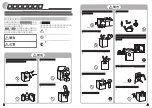
Figure 1


B

A

C


Outlet

Inlet

Summary of Contents for PGK Series

Page 1: ...NG INSTRUCTION Duct cooler for cold water for mounting in rectangular ventilation ducts IMPORTANT Read these instructions before using the product Save the instructions for future use 8 DE MONTAGEANLE...

Page 2: ...fl ktmotorn och an dra komponenter r l mpliga f r den fuktiga luften efter kylaren Kanalkylaren m ste isoleras utv ndigt s att det inte bildas kon dens p utsidan Normalt m ste ven kanalerna som trans...

Page 3: ...ng av droppl dan Tag bort droppl dan genom att ppna exenterl sen p framsida S nk droppl dan ca 2 3cm och skjut den d refter bak t f r att frig ra l smekanismen p baksidan Droppl dan h nger fast i ett...

Page 4: ...4 1944 74 30 45 18 9 9 0 0 36 16 7 2592 107 25 50 17 6 6 6 0 26 9 5 2592 120 30 45 19 8 10 8 0 43 23 3 Kapacitet PGK 500 250 3 2 0 Vattentemperatur 6 12 C Luftfl de Tryckfall luft Luft in Luft in Luft...

Page 5: ...1 5144 86 30 45 18 8 23 7 0 94 17 8 6858 117 25 50 17 5 17 6 0 70 10 3 6858 140 30 45 19 8 28 2 1 12 24 5 Kapacitet PGK 700 400 3 2 0 Vattentemperatur 6 12 C Luftfl de Tryckfall luft Luft in Luft in...

Page 6: ...30 8 1944 95 30 45 19 0 11 0 0 44 15 2592 153 25 50 17 4 9 3 0 37 11 2592 153 30 45 19 8 13 6 0 54 23 Kapacitet PGK 500 250 4 2 0 Vattentemperatur 6 12 C Luftfl de Tryckfall luft Luft in Luft in Luft...

Page 7: ...9 5144 154 30 45 15 5 33 3 1 32 22 6858 203 25 50 15 4 24 0 0 95 12 6858 250 30 45 16 7 40 1 1 59 30 Kapacitet PGK 700 400 4 2 0 Vattentemperatur 6 12 C Luftfl de Tryckfall luft Luft in Luft in Luft...

Page 8: ...at the fan motor and other components will not be harmed by the humid air downstream of the cooler The duct cooler must be insulated on the outside so that no condensate will form The ducts that carry...

Page 9: ...the connection so that any remaining condensate will not run out Remove the drip tray by releasing the excentric lock on the front Lower the drip tray about 2 3 cm and then move it towards the back so...

Page 10: ...4 1944 74 30 45 18 9 9 0 0 36 16 7 2592 107 25 50 17 6 6 6 0 26 9 5 2592 120 30 45 19 8 10 8 0 43 23 3 Capacity PGK 500 250 3 2 0 Water temperature 6 12 C Air flow Press drop Inlet air temp Inlet air...

Page 11: ...1 5144 86 30 45 18 8 23 7 0 94 17 8 6858 117 25 50 17 5 17 6 0 70 10 3 6858 140 30 45 19 8 28 2 1 12 24 5 Capacity PGK 700 400 3 2 0 Water temperature 6 12 C Air flow Press drop Inlet air temp Inlet...

Page 12: ...30 8 1944 95 30 45 19 0 11 0 0 44 15 2592 153 25 50 17 4 9 3 0 37 11 2592 153 30 45 19 8 13 6 0 54 23 Capacity PGK 500 250 4 2 0 Water temperature 6 12 C Air flow Press drop Inlet air temp Inlet air...

Page 13: ...9 9 5144 154 30 45 15 5 33 3 1 32 22 6858 203 25 50 15 4 24 0 0 95 12 6858 250 30 45 16 7 40 1 1 59 30 Capacity PGK 700 400 4 2 0 Water temperature 6 12 C Air flow Press drop Inlet air temp Inlet air...

Page 14: ...rden wenn man nicht sicher ist ob Gebl semotor und andere Komponenten f r die feuchte Luft nach dem K hler geeignet sind Der Kanalk hler mu au en w rmeged mmt werden damit sich auf der Au enseite kein...

Page 15: ...ser nicht ausl uft Entfernen Sie den Tropfbeh lter indem Sie zuerst die Exzen terverschl sse an der Vorderseite ffnen Senken Sie den Tropf beh lter dann ca 2 3 cm ab und schieben Sie ihn nach hinten u...

Page 16: ...4 1944 74 30 45 18 9 9 0 0 36 16 7 2592 107 25 50 17 6 6 6 0 26 9 5 2592 120 30 45 19 8 10 8 0 43 23 3 Leistung PGK 500 250 3 2 0 Wassertemperatur 6 12 C Luftstrom Druckverlust Zuluft Zuluft Abluft Le...

Page 17: ...1 5144 86 30 45 18 8 23 7 0 94 17 8 6858 117 25 50 17 5 17 6 0 70 10 3 6858 140 30 45 19 8 28 2 1 12 24 5 Leistung PGK 700 400 3 2 0 Wassertemperatur 6 12 C Luftstrom Druckverlust Zuluft Zuluft Abluf...

Page 18: ...30 8 1944 95 30 45 19 0 11 0 0 44 15 2592 153 25 50 17 4 9 3 0 37 11 2592 153 30 45 19 8 13 6 0 54 23 Leistung PGK 500 250 4 2 0 Wassertemperatur 6 12 C Luftstrom Druckverlust Zuluft Zuluft Abluft Le...

Page 19: ...9 9 5144 154 30 45 15 5 33 3 1 32 22 6858 203 25 50 15 4 24 0 0 95 12 6858 250 30 45 16 7 40 1 1 59 30 Leistung PGK 700 400 4 2 0 Wassertemperatur 6 12 C Luftstrom Druckverlust Zuluft Zuluft Abluft Le...

Page 20: ...t 556138 3166 VAT no SE556138316601 Postal Cheque Service 48 51 08 5 Bank Transfer 926 0365 Fax Int 46 451 410 80 E mail veab veab com Phone Int 46 451 485 00 Website www veba com NB We reserve us fro...

Reviews: