7
11.03
Vedolux 30
Illustrations may differ from the actual product
Allowing for printing errors and errors on proofs
Installation
Function.of.accumulator.control
The accumulator control ensures that the boiler reaches a high
working temperature before it starts charging the accumulator tank.
It also prevents the return temperature to the boiler falling too low,
helping to minimise the risk of condensation in the combustion
chamber.
The charging pump of the accumulator system is controlled by a flue
gas thermostat.
Expansion.system
The boiler is connected to a vented or unvented expansion system.
The volume of the expansion vessel is dimensioned according to
the circumstances. The guideline values for volume are approx.
5 % of the total system volume for vented systems, or 13- 15 % for
unvented systems.
Vented
The distance between the top of the highest radiator and
the expansion vessel must be at least 8.2 ft in order to pre-
vent oxygen saturation of the water in the heating system.
The expansion vessel is connected in a continuous and
unisolatable rise from the boiler’s expansion connection.
To prevent damage occurring if the expansion system fails,
for example because of freezing, the boiler should be fitted
with a type approved safety valve, 21.8 psi.
Unvented In unvented systems, the boiler must be fitted with a type
approved safety valve, 21.8 psi, connected using an uniso-
latable pipe from the connection at the top of the boiler, as
well as a bleed valve.
The expansion vessel is best connected using ½” copper-
pipe, as shown in the diagram on the previous page.
The opening pressure of the safety valve is based on the
lowest maximum pressure that any system component
can withstand.
Coolin
g.coil.-.temperature.limiter
The boiler system must be equipped with a temperature limiter in
accordance with the applicable regulations.
The boiler has a cooling coil which, combined with a suitable thermal
valve, is used to prevent the boiler temperature exceeding 230°F if
the water boils. Follow the instructions of the va
lve manufacturer.
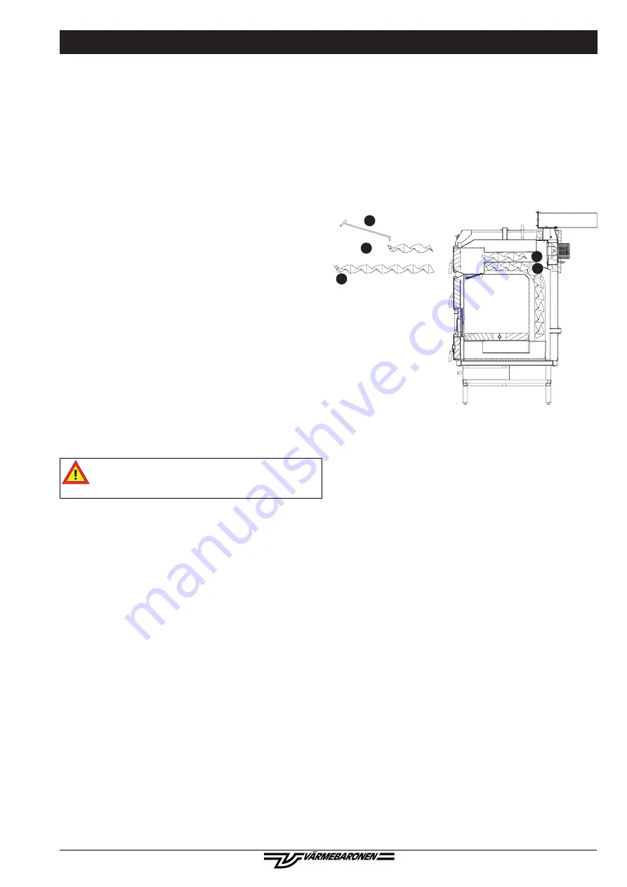
Turbulators
The five turbulators are installed in the flue gas pipes as shown in
the diagram. The purpose of the turbulators is to introduce turbu-
lence to the flue gases, causing more heat to be transferred to the
boiler water.
If the flue gas temperature falls too low (with a wide and long chim-
ney), there is a risk of condensation in the flue duct. To increase the
temperature, the three upper turbulators can be removed, or cut to
a length that produces a suitable flue gas temperature The draught
hatch is another way of reducing condensation problems.
Bracket.for.cleaning.tool
The bracket for the cleaning tool can be fitted to either side of the
boiler or any suitable place close to the boiler.
Draught.hatch
An extremely high chimney and/or strong winds can create a draught
that is strong enough to allow combustion with the fan turned off.
The solution is to install a draught hatch, which can reduce the
draught to 0.04 - 0.06 in. water.
Pellet.burner/oil.burner
The Vedolux 30 is primarily designed to be fired by firewood, but can
also be modified for pellets using a pellet burner.
When the pellet burner is used, the accessories supplied with the
pellet hatch set must be installed:
• Hatch, designed for the Viking Bio pellet burner.
• Cover plate with draught hatch, instead of the fan on the rear of the
boiler.
• Cover plates for the primary damper behind the plate on the front
of the boiler.
• Cover plate for the secondary damper.
It is possible to install an oil burner in the pellet hatch set. Fittings are
available.
Because of the risk of condensation you should monitor the flue gas
temperature. Check that the flue gas temperature is appropriate for
the chimney type.
Otherwise, follow the instructions of the burner manufacturer.
x 3
x 2
30
31
30
31
29


