The appliance must be installed in accordance
with national wiring regulations by a qualified and
authorized installer. If the supply cord is
damaged, it must be replaced by the
manufacturer, its service agent or similarly
qualified personnel in order to avoid a hazard.
The heat pump is equipped with a 1,8 metre power
supply cord, 3G x 1.5 mm2, which comes out on the bottom
of the device with stress relief bushing and a safety plug. The
socket should be protected individually by an automatic circuit
breaker and a residual-current circuit breaker (30mA).
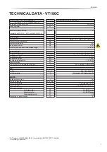
Max. power input: See “page 6-7 - Technical data”.
Power supply:
230V AC Phase - Neutral - Earth, 50Hz
Mains lead colours: Phase – brown,
Neutral
–
blue,
Earth
–
yellow/green
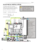
ELECTRICAL DIAGRAM
Display
Operation capacitor for fan
(Fan - 2 µF - R2E180)
Capacitor, fan speed
(Fan - 6 µF - R2E180)
Start capacitor compressor
(Compressor -
80 µF
- DLE6.5CN)
Heating element
(2kW)
Thermostat for heating element
X
Thermostatic max. switch
Compressor
(DLE6.5CN)
Fan
(R2E180)
Solenoid valve
(Only for -10°C units)
Start relay
(Compressor)
Earth connection
(X1 / X2)
Heating cable for compressor
(Only for -10°C units)
CN1-4: 230V AC
CN5-6: 5V DC
S1
C3
E1
N3
F2
M1
M2
SV1
K1
HC
C1
C2
E1
Blue
Red
Brown
Blue
Brown
Brown
Brown
Brown
CN3
CN4
8
7
6
5
4
3
2
1
4
3
2
1
N3
SV1
C2
M2
M
L
N
Black
Blue
Blue
Blue
Blue
Blue
C1
Orange
F2
CN2
6
5
4
3
2
1
CN1
2
1
L
N
CONTAINER
Earth
Earth
Earth
Earth
Earth
Earth
Earth
PV / HP
(T3)
(External connection)
Container
Temp.
Sensor ( °C )
Evaporator T
emp.
Sensor ( °C )
DrawDwon.
Temp.
(External connection)
PV / EL
(T4)
(External connection)
CN5
CN6
1
2
3
4
5
6
1
2
3
4
5
6
7
8
CN10
CN9
CN7
S1
X2
X1
RELAIS 1
RELAIS 2
RELAIS 3
RELAIS 4
RELAIS 5
RELAIS 6
RELAIS 7
M1
M
10
14
13
11
Brown
Brown
Blue
Blue
C3
K1
Black
Black
Blue
Brown
HC
ELECTRICAL INSTALLATION
ENGLISH
18


