Varian 919-1115 Instruction Manual Download Page 22

TECHNICAL INFORMATION 

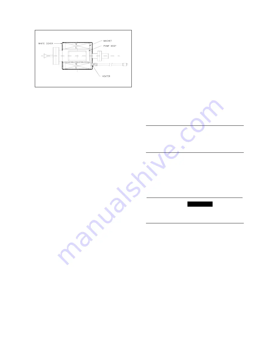
Fig. 18 - Heater element mounting 

(cover removed) 

HEATER REPLACEMENT 

To replace the pump heaters, first remove the 
faulty heater following, in the reverse order, the in-
structions of the paragraph “HEATER 
INSTALLATION”, and then reassembly the new 
heater following the instructions of the above men-
tioned paragraph. 

BAKEOUT OPERATION 

When a VacIon pump does not reach the desired 
base pressure, and there are no leaks, it is neces-
sary to bake the system. This is done by heating 
the pump and all the components in the system, 
and is generally required to achieve base pres-
sures less than 10

-8

 Torr (mbar). 

1. Heat the pump body and the system with a 

bakeout oven unit or heating strips to tempera-
tures between 150 °C and 250 °C (250 °C is 
the maximum allowable for most bakeable high 
voltage cables). This temperature is high 
enough to degas the pump surfaces of water 
vapor without damaging the magnet and high 
voltage connector. Note that the system com-
ponents must be compatible with the bakeout 
temperature. The heating must be approxi-
mately even on all surfaces or evaporated wa-
ter will condence on the colder surfaces 
resulting in an incomplete bake and preventing 
achievement of UHV vacuum pressure. 

2.  Leave the pump control unit on and monitor the 

pressure. Varian recommends that current dur-
ing bake not exceed 10 mA; if this value is ex-
ceeded, turn the bakeout off and then on again 
when low pressure is restored. To control the 
heaters and to monitor the high pressure limit 
during bakeout, an automatically controlled re-
lay may be used. 

3. Bake the VacIon 

Plus

 pump for at least 24 

hours. Longer bakeout periods are recom-
mended when the pump has been used with 
heavy gas loads or when UHV pressure, 10

-9


Torr (mbar) or less is desired. 

4. As the pump and system cool down to room 

temperature, a drop in pressure should be ob-
served. 

Note that the ion pump can be also baked when 
switched off, into an external turbo pump through a 
bakeable isolation valve. This method gives the 
best vacuum performance. 

Bakeout of VacIon pump with the integral  
heaters 

1.  The integral heaters are to be powered with the 

appropriate voltage. (Please refer to the 
inscription on the heaters to apply correct volt-
age). 

2.  The integral heaters are designed to provide a 

temperature of 250 °C to 300 °C when the 
pump is wrapped in a 3-fold aluminum foil. 

NOTE 

A three-layer foil wrapping is advisable and suffi-
cient to achieve full bakeout/regeneration if the 
standard European heaters (220 Vac) are oper-
ated at 240 Vac, thus preventing overheating. 

3.  Bakeout the VacIon pump for 24 hours. If the 

pump is used in heavy gas load applications, it 
is recommended to bakeout the pump for a 
longer period. 

4.  Wait until the pump cools down to room tem-

perature and recovers its base pressure before 
using it in the application. 

,

WARNING!


Do not touch the pump during the heating and 
cooling phases. The high temperature may cause 
serious damage. 

OPERATING PROCEDURE 

1.  Using a clean roughing pump, evacuate the 

system to a minimum starting pressure per the 
charts on pages from 10 to 12 for the type of 
ion pump. 10

-4

 Torr (mbar) or less is recom-

mended. A turbo-molecular roughing pump is 
recommended. 

2.  When starting an ion pump, a slight increase 

in vacuum pressure is normal as the internal 
components are heated and outgassed. If 
possible leave the roughing pump connected 
to the system while starting the ion pump. This 
will make the startup faster and easier. 

3.  Connect the control unit to a suitable power 

source and switch the power on. 

4.  Switch on high voltage to the pump and ob-

serve the current and voltage. Fastest starting 
is obtained using a high applied voltage, 7 kilo-
volts for example. The applied voltage may be 

 17 

87-900-106-01(B) 

Summary of Contents for 919-1115

Page 1: ...del 919 1115 Model 919 1125 Model 919 1145 Model 919 1146 Model 919 1114 Model 919 1124 Model 919 1144 I MANUALE DI ISTRUZIONI D BEDIENUNGSHANDBUCH F NOTICE DE MODE D EMPLOI GB INSTRUCTION MANUAL 87 9...

Page 2: ...VacIon Plus 20...

Page 3: ......

Page 4: ......

Page 5: ...Vacuum evaluation 14 Short circuits 14 TYPICAL INSTALLATION 14 INLET FLANGE CONNECTION 15 CONTROL UNIT CONNECTION 16 SAFETY INTERLOCK 16 HEATER INSTALLATION 16 HEATER REPLACEMENT 17 BAKEOUT OPERATION...

Page 6: ...engono informazioni importanti estrapolate dal te sto PREPARAZIONE PER L INSTALLAZIONE La pompa viene fornita in un imballo protettivo speciale se si presentano segni di danni che potrebbero essersi v...

Page 7: ...zione all aria il deposito del composto di titanio assorbe vapore acqueo in con seguenza di ci al successivo avvio il riscaldamento della pom pa provoca il rilascio del vapore e di parte dell idrogeno...

Page 8: ...hr besteht ACHTUNG Die Warnhinweise vor bestimmten Prozeduren machen den Bediener darauf aufmerksam da bei Nichteinhaltung Sch den am Ger t entstehen k nnen W hrend des Betriebes soll die Umgebungstem...

Page 9: ...stromwert der Steuereinheit ann hert weist auf eine Leckstelle an der Pumpe und am System hin Ein zeitweiliger Anstieg des Vorvakuumdruckes ist w hrend der Anlaufphase nor mal 4 W hrend des Anlaufes d...

Page 10: ...fonctionne ment pour respecter les sp cifications techniques d clar es la temp rature ambiante doit tre comprise entre 0 C et 85 C ATTENTION Les messages d attention apparaissent avant certaines proc...

Page 11: ...400 V Une valeur de courant proche du courant de court circuit de l unit de contr le r v le l existence d une fuite dans la pompe et dans le syst me Au cours de la phase de d marrage un accroissement...

Page 12: ...in explosive environments or those with a high fire risk Dur ing operation to obtain the specified operation the ambient temperature must be between 0 C and 85 C CAUTION The caution messages are displ...

Page 13: ...umped hydrogen thus the starting time may be lengthened CAUTION Do not put any electronic device near the pump otherwise the magnetic field around it may cause a device malfunctioning MAINTENANCE Oper...

Page 14: ...ty high voltage supply is required to operate Diode and Noble Diode pumps A nega tive polarity high voltage supply is required to op erate StarCell pump since the anode is grounded and the cathode is...

Page 15: ...ate the VacIon Plus 20 pump it normally requires an amount of gas equal to 0 6 Torr litres mbar litres Consequently pumps can operate for extended periods of time at low pressures in the non saturated...

Page 16: ...TECHNICAL INFORMATION VACION PLUS 20 NOBLE DIODE Fig 6 Pumping speed vs pressure for Nitrogen Fig 7 Pumping speed vs pressure for Argon Fig 8 Pressure vs current diagram 11 87 900 106 01 B...

Page 17: ...0 DIODE Fig 9 Pumping speed vs pressure for Nitrogen Fig 10 Pressure vs current diagram OUTLINE DRAWING The following figure shows the outline drawing for the VacIon Plus pump Fig 11 VacIon Plus pump...

Page 18: ...ne of the pump and in the plane of the flange as a function of distance from the pump are shown in Figs 13 14 and 15 Fig 12 VacIon Plus pump axis identification Fig 13 Stray magnetic field along X axi...

Page 19: ...or an indication of one of the following conditions If the pump is free of leaks and is at a low pressure the pressure indication shall within 10 minutes fall to or below the 10 8 Torr mbar range as t...

Page 20: ...nal vacuum using pliers to open the copper tube pinch off CAUTION Do not open the pinch off seal with a saw or grinder These methods will cause metal particles to be drawn into the pump by the inrushi...

Page 21: ...or blanked off WARNING Before removing the high voltage connector of the cable from the control unit be sure the main power is removed from the control unit Wait at least 10 seconds after removing the...

Page 22: ...the pump and system cool down to room temperature a drop in pressure should be ob served Note that the ion pump can be also baked when switched off into an external turbo pump through a bakeable isola...

Page 23: ...it be sure the main power is removed from the control unit Before removing the high voltage connector of the cable from the control unit be sure the main power is removed from the control unit Wait at...

Page 24: ...emis sion current high potting should be performed High potting is the term used to describe the ap plication of higher than normal operating voltage 10 12 KV 20 50 mA for the purpose of burning off...

Page 25: ...and pump Subse quent reduction in pressure de pends on the rate of depletion of this vapour Heavy hydrocarbons are most troublesome because of their relative low vapour pressure and they are very diff...

Page 26: ...Ferrite magnets 919 0040 919 0039 919 0035 Samarium Cobalt magnets 919 0036 Heaters 120V 220V 919 0044 919 0043 Copper gasket for 2 3 4 inlet flange 10 pack individually sealed FG 0275 CI Nut and bolt...

Page 27: ...0 Vac 2 Neg 120 Vac 1 Pos 120 Vac 2 Pos 230 Vac 1 Neg 230 Vac 2 Neg 230 Vac 1 Pos 230 Vac 2 Pos 929 7008 929 7009 929 7010 929 7011 929 7012 929 7013 929 7014 929 7015 MidiVac 120 Vac with single outp...

Page 28: ...TIFICATION Product Description Varian P N Varian S N Purchase Reference TYPE OF RETURN check appropriate box Paid Exchange Paid Repair Warranty Exchange Warranty Repair Loaner Return Credit Shipping E...

Page 29: ...rate No zero high backround Gauge tube not working Display problem Vacuum system unstable Cannot reach test mode Communication failure Degas not working Failed to start Other Error code on display Oth...

Page 30: ...1263 Toll Free 0120 655 040 Korea Varian Technologies Korea Ltd Shinsa 2nd Bldg 2F 966 5 Daechi dong Kangnam gu Seoul Korea 135 280 Tel 82 2 3452 2452 Fax 82 2 3452 2451 Toll Free 080 222 2452 Mexico...

Reviews: