Setup
Setup
Setup
Setup
Setup
10
19
1.
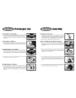
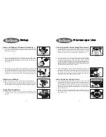
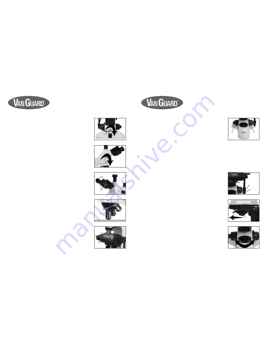
Focusing adjustment is achieved by turning the coarse/fine focus controls
located on both sides of the microscope. The large knob is used for coarse
adjustment, the smaller knob for fine adjustment (figure 48). The coaxial
arrangement allows for easy, precise adjustment without stage drift.
Focusing and Mechanical Stage Mechanisms
Microscope Use
Microscope Use
Microscope Use
Microscope Use
Microscope Use
Figure 49
Figure 50
Figure 51
3.
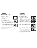
The mechanical stage X-Y controls, located underneath the right-hand side
of the stage (figure 49), provide easy and accurate positioning of the
specimen. One complete turn of the longitudinal (Y-axis) control (lower half
of the stage controls) will move the specim
en 20mm left or ri
ght. One
complete turn of the transverse (X-axis) control (upper half of the stage
controls) will move the s
pecimen 33mm front or ba
ck.
2.
Turning the coarse/fine focus control raises and lowers the stage vertically.
One complete turn of the fine focusing knob ra
ises or lowers the stage
0.2mm; the smallest graduation refers to 2 microns of v
ertical movement.
One half turn of the coarse focusing knob raises
or lowers the stage 20mm.
To ensure long life, turn the focusing knobs slowly and uniformly. Care should
always be taken when using the focus controls to prevent the objectives
from making contact with the stage or specimen.
Abbe Condenser Swing-In Lens
4.
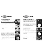
The transmitted illumination Abbe condenser features a swing-in lens located
at the bottom of the condenser (figure 50). This lens should be swung into
the light path when using the 5X objective only. This is necessary to obtain
the correct Numerical Aperture required for the low powered objective. In
addition you will need to fully open the aperture iris in order to prevent
vignetting and leave the condenser height the same as when originally setup
using the 10X objective.
5.
To control contrast in your specimen image while operating with the 5X
objective use the field diaphragm (figure 51) instead of the aperture diaphragm
that is typically used.
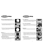
7.
Insert the round electrical plug from the lamp housing into the jack located
on the rear of the stand (figure 6). Tighten the outer collar to prevent the
cable from coming loose.
Head and Reflected Illuminator Assembly
(cont.)
Objective Installation
10.
Adjust the coarse focus knobs so that the stage is completely lowered.
11.
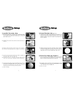
Remove the objectives from their packing canisters and thread each one
into the nosepiece holes ensuring they are fully seated (figure 9). Typically
they are installed in numerical order from lowest to highest magnification.
Figure 6
Figure 7
Figure 8
Figure 9
Figure 10
8.
Insert the dovetail flange located on the bottom of the head into the hole at
the top of the reflected illuminator. The eyetubes should be facing forward.
While still holding the head
tighten the head setscrew with the 2mm hex
wrench (figure 7).
9.
Remove the two packing caps from the eyetube openings and set aside
with the other packaging as they will not be needed. Slide the eyepieces into
the eyetubes and ensure they are fully seated. If you wish you may attach
the eyecups to the ends of the eyepieces, though this step is optional and
eyeglass wearers especially may choose not to install the them (figure 8).
Stage Plate Installation
12.
With the stage completely lowered place the glass stage plate into the
rectangular recess on top of the stage (figure 10). Clean the plate first if
necessary.
collar
eyepieces
eyecups
objectives
stage plate
Figure 48
right side
focus
controls
left side
focus
controls
y-axis
x-axis
swing-out lens
field diaphragm


