22
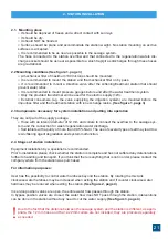
2.4 .1 Installation stages of CONFORT stations
• Set the station in the decided spot while observing the conditions under items 2.1 and 2.2.
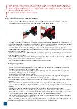
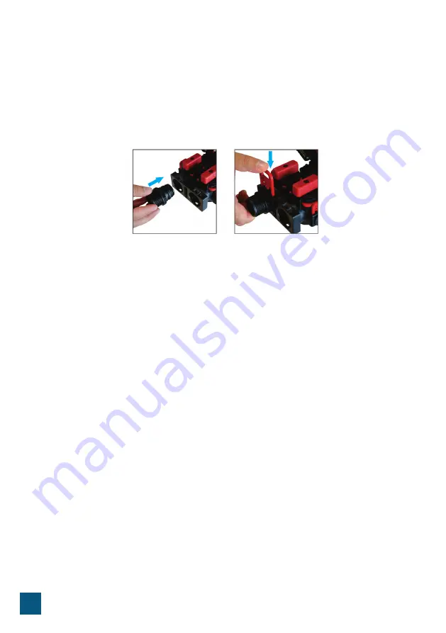
• Introduce the connectors in the by-pass as shown in the figure below.
• Connect the supply installation to the station by-pass
(
See figure 4, page 4)
, at the inlet with „→”
sign oriented towards the station (the treatment station is supplied with a pre-mounted by-pass
system, the two by-pass connections are with 1” with an exterior thread.
• To connect the pipes to the station by-pass you should use packing materials (teflon etc.)
• Water installation to consumers is connected to the by-pass, on the outlet with „→” sign oriented
towards the station exterior
.
• Connect the overflow outlet of the station to the sewage system by means of the purchased 12 mm
hose and 12-22 mm collars.
• Connect the
regeneration water discharge connection
of the station to the sewage system by
means of the 12 mm hose and the 12-22 mm collars.
• Make sure that by-pass is in by-pass position (with valves closed)
Putting into operation:
• During the entire period of installation, the by-pass valves are closed (no water in the station).
• Connect the power supply to the control valve;
• The connection to power supply will be achieved through the 12V transformer to be equipped.
• The control valve panel will be monitored.
• Air is discharged from the station, namely:
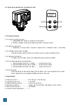
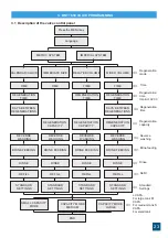
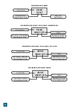
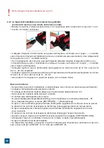
- Press the SET button “■” until it enters the manual regeneration interface [MAN. REG.] [MAN.
REG. IMMEDIATE] and then press [Menu] to start regeneration.
- A by-pass valve ½ drive is opened from the entry to the station as signalled by an arrow towards
the valve.
- It should be checked whether water flows in the wash/regeneration water discharge hose.
• The by-pass valve from the entry to the station is entirely open, as signalled by an arrow towards
the valve.
• It should be checked whether clean water flows through wash water discharge hose.
• When the water is clear, press the '▼' key successively until the valve reaches service position.
• If the water is not clear or the air is not completely removed from the vessel and the valve passes
at the next regeneration stage [BRINE], press the '▼' key and advance to [RINSE].
• If even after the [RINSE] stage the water is not clear, the manual regeneration cycle is repeated.
• The outlet valve of the station is opened.
• Where available, deflate and remove the air cushion from the brine pot and feed the pot with salt
and approximately 4 litres for CONFORT 12.5 and 8 litres for CONFORT 25.
Do NOT connect the station directly to 220 V.
!
Make sure that there is a gravity flow in the hoses making the connection between overflow, the
connection for wash/regeneration water discharge and the sewage system. Make sure that hoses
are not clogged and that water in the sewage system cannot backwater there at overflow outlet
and the discharge outlet, respectively.
!
Summary of Contents for CONFORT Series
Page 63: ...63 2 2 1 2 2 1 4 100 12 1 4 2 3 12 99 5 NaCl 2 4 2 5 service bypass 3 5 12 12 22...
Page 68: ...68 3 5 4 09 00 CC 07 09 00 IM 01 12T 09 00 IM 01 12T 09 00 VM 01 12T...
Page 69: ...69 4 1 2 REGION 3 4 5 6 7 REG CAP 8 9 10 11 12...
Page 71: ...71 4 5 6 Figure 5...
Page 75: ...75 AquaPUR SC Valrom Industrie SRL www valrom ro www aqua pur ro 1 aquaPUR CONFORT BG...
Page 77: ...77 2 2 1 2 2 1 4 100 12V 1 4 2 3 12 99 5 NaCl 2 4 2 5 bypass 3 5 12 12 22...
Page 82: ...82 3 5 4 09 00 CC 07 09 00 IM 01 12T Tone 09 00 IM 01 12T Tone 09 00 VM 01 12T Tone...
Page 83: ...83 4 1 2 REGION 3 4 5 6 7 REG CAP 8 9 10 11 12...
Page 85: ...85 4 5 6 Figure 5...
Page 88: ...88 6 SOFT 42 dH 0 20 0 05 6 SOFT 42 dH 0 20 0 05 Valrom Tel 4 0724 200 005...

