background image

                A V I O N I C S   L I M I T E D


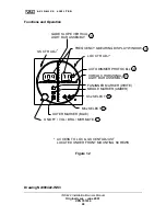
Functions and Operation 

ON/OFF / VOL / BRG / MKR MUTE

OUTER MARKER (BLUE)

GS CTR ADJ *

LOCATED UNDER FRONT MOUNTING SCREWS

ACCESS TO LOC & GS CENT ADJUST

MIDDLE MARKER (AMBER)

FAN/INNER MARKER (WHITE)

Mhz SELECT

1

4

Khz SELECT

*

5

VOR/LOC HORIZONAL

FREQUENCY & BEARING DISPLAY WINDOW

AUTO DIMMER PHOTOCELL

LIGHT BAR ASSEMBLY

LOC CTR ADJ

6

2

*

3

LIGHT BAR ASSEMBLY

GLIDE SLOPE VERTICAL

7


Figure 1.2 


Drawing No900422-INS3 

INS 422 Installation/Owners Manual  

Original Issue – June 2001 

VPN 701034 

22


Summary of Contents for INS 422

Page 1: ...OriginalIssue 1 AVIONICS LIMITED INS 422 Integrated Navigation System Installation Owners Manual VPN 701034 June 2001 ...

Page 2: ...l continually improve product quality and performance Information contained in this document is subject to change at any time without notice This document may not be reproduced or transmitted by any means without consent of VAL Avionics Ltd Is a registered trademark of VAL Avionics Ltd AVIONICS LTD P O Box 13025 Salem Oregon 97309 503 370 9429 INS 422 Installation Owners Manual Original Issue June...

Page 3: ...ph 1 1 INTRODUCTION 1 2 DESCRIPTION OF EQUIPMENT 1 3 TECHNICAL CHARACTERISTICS 1 4 UNITS AND ACCESSORIES REQUIRED SUPPLIED 1 5 ACCESSORIES REQUIRED NOT SUPPLIED 1 6 LICENSE REQUIREMENTS 1 7 STATEMENT OF COMPLIANCE INS 422 Installation Owners Manual Original Issue June 2001 VPN 701034 2 ...

Page 4: ...vionics Cooling Requirements for Panel Mounted Equipment 2 3 2 Pre Installation Information 2 3 3 Antenna Installation 2 3 4 Audio Interface 2 3 5 Harness Assembly and Installation Hardware 2 4 Post Installation Check 2 4 1 Post Installation Adjustments 2 4 2 Periodic Maintenance INS 422 Installation Owners Manual Original Issue June 2001 VPN 701034 3 ...

Page 5: ... O P E R A T I O N 1 3 W I R E C O L O R A N D F U N C T I O N 1 4 I N S T A L L A T I O N I N T E R C O N N E C T D I A G R A M 1 5 A L I G N M E N T A C C E S S L O C A T I O N S 1 6 B N C A N D C A B L E A S S E M B L Y 1 7 P 1 2 0 1 M E C H A N I C A L A S S E M B L Y Revision History APPENDIX A E N V I R O N M E N T A L Q U A L I F I C A T I O N F O R M APPENDIX B M A N U F A C T U R E R S W ...

Page 6: ...ntegrated Navigation System Follow the procedures outlined in this manual for successful installation and designed performance 1 2 DESCRIPTION OF EQUIPMENT The INS 422 Integrated Navigation System is a quality manufactured panel mounted digital synthesized instrument approach receiver covering the aviation frequencies for Localizer Receiver 108 1 111 975 MHz Glideslope Receiver 329 15 335 0 MHz Ma...

Page 7: ...er VPN 807000 Current 1 8 Amp Receive Receiver VHF Frequency VOR LOC 108 00 to 117 95 MHz Sensitivity 2 µV to provide 50 Standard Deflection Channel Spacing VOR LOC 50 Khz UHF Frequency Glideslope 329 15 to 335 0 MHz Sensitivity 20 µV to provide 50 Standard Deflection Channel Spacing Glideslope 150 Khz Marker Receiver 75 MHz AGC Characteristics From 10 µV to 200 µV the audio level will not vary mo...

Page 8: ...A V I O N I C S L I M I T E D INS 422 Installation Owners Manual Original Issue June 2001 VPN 701034 7 ...

Page 9: ...STATEMENT OF COMPLIANCE This equipment has been tested in accordance with the requirements contained in the appropriate Commission Regulations To the best of my knowledge these tests were performed using measurement procedures consistent with industry or Commission standards and demonstrate that the equipment complies with the appropriate standards Each unit manufactured imported or marketed as de...

Page 10: ...instructions the INS 422 will perform as specified and provide excellent performance to meets its design 2 2 UNPACKING AND INSPECTING EQUIPMENT Exercise care when unpacking the equipment Visually inspect the unit for any evidence of damage incurred during shipping It is advisable to retain the shipping carton and packing material should it be necessary to return the unit If a damage claim needs to...

Page 11: ...o the contemporary high density packaging techniques Although the INS 422 does not require forced air cooling the combined heat generated by several units operating in the typical panel within close proximity may significantly degrade the reliability to the equipment if provisions for adequate cooling are not incorporated in the initial installation 2 3 2 PRE INSTALLATION INFORMATION Always follow...

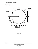
Page 12: ... instrument mounting cutouts If the location you have selected requires that a mounting hold be cut refer to Figure 1 0 on Page 19 for the mounting template Mark and cut the mounting holes as required Position the unit in its upright position and from the rear of the panel place the unit into the selected 3 125 panel cutout With the unit held in place insert four of the supplied 6 32 X 3 8 screws ...

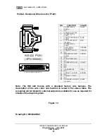
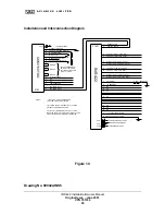
Page 13: ...ARE Val Avionics Ltd supplies the harness assembly and three BNC connectors required The INS 422 will require that a 5 amp circuit breaker or fuse be used for circuit protection The wire functions and color codes for P1205 are specified in Figure 1 3 Page 22 The Automatic Radial Centering feature can be accessed and operated when the remote momentary pushbutton switch VPN 501117 is installed Refer...

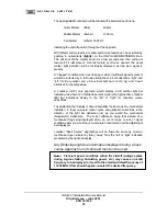
Page 14: ... relation to the ILS runway Check the Glideslope accuracy in relation to the published ILS approach altitude Verify the three light marker operations and audio at published locations depicted on the approved approach flown When Marker audio is present a marker audio mute feature can be activated by pushing in momentarily lightly on the ON VOL MKR MUTE BRG knob This will shut off the marker audio f...

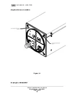
Page 15: ...ight bar Replace mounting screw B Glideslope Centering Remove top left mounting screw on front panel and with a small flat blade screwdriver turn R12004 left or right until only a center light remains on the light bar Replace mounting screw C VOR Balance Access to the VOR Balance adjust pot R412 is through a 1 8 hole on the right side of the unit approximately 5 from the front and 1 from the top A...

Page 16: ...ted to have a high degree of reliable performance Varied use and extreme climatic conditions over time can alter normal performance such to require minor calibration and or cleaning of the INS 422 unit In addition to monthly VOR accuracy checks for IFR flight it is important that the INS 422 system be serviced by the factory or its authorized representatives any time the VOR accuracy checks show t...

Page 17: ... power up the INS 422 system by rotating the knob slightly clockwise out of the off detent position Continue to turn clockwise and adjust for a comfortable receive audio level for monitoring during the selected approach 3 2 CONTROLS Controls and accessories of the front panel are Refer to Figure 1 2 Page 21 1 On Volume Marker Mute Bearing 2 Auto Dimmer Photocell 3 Frequency and VOR Bearing Display...

Page 18: ...Front Course of the approach would be as follows A single center lamp displayed without any barring up down or left right would indicate a centered on course and glidepath indication for both Glidepath and Localizer A light bar deflection string of lamps to the right would indicate a left of course condition and would require a turn right in the direction of the light bar to adjust and correct cou...

Page 19: ...ppropriate Localizer light bar indications display to the left or right for Localizer course corrections The digital light bar display is flown essentially the same as any mechanical indication in that you would make course and glidepath corrections in the direction of the light bar deflection just as you would the mechanical Needle arm deflections The minor difference being that instead of a mech...

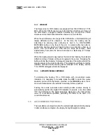
Page 20: ...leasing the button will stop the stepping Subsequent pressing of the button will start the stepping slowly in the opposite direction This procedure will finally center the indicator at which time the bearing will be indicated in the display and the TO or FROM ambiguity will also be displayed 3 3 4 AUTOMATIC RADIAL CENTERING To determine the bearing TO a VOR station with conventional course indicat...

Page 21: ...A V I O N I C S L I M I T E D Mounting Template Figure 1 0 INS 422 Installation Owners Manual Original Issue June 2001 VPN 701034 20 Drawing No 900422 INS1 ...

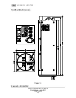
Page 22: ...A V I O N I C S L I M I T E D Front Rear Side Dimensions Figure 1 1 Drawing No 900422 INS2 INS 422 Installation Owners Manual Original Issue June 2001 VPN 701034 21 ...

Page 23: ...TO LOC GS CENT ADJUST MIDDLE MARKER AMBER FAN INNER MARKER WHITE Mhz SELECT 1 4 Khz SELECT 5 VOR LOC HORIZONAL FREQUENCY BEARING DISPLAY WINDOW AUTO DIMMER PHOTOCELL LIGHT BAR ASSEMBLY LOC CTR ADJ 6 2 3 LIGHT BAR ASSEMBLY GLIDE SLOPE VERTICAL 7 Figure 1 2 Drawing No900422 INS3 INS 422 Installation Owners Manual Original Issue June 2001 VPN 701034 22 ...
Page 24: ...auto pilot system PIN FUNCTION COLOR 1 GLIDESLOPE DOWN WHITE 2 NC 3 VOR LOC FLAG 4 GLIDESLOPE FLAG 5 VOR LOC RECEIVER AUDIO BLUE 6 13 75 VDC INPUT 20 AWG RED 7 GLIDESLOPE FLAG 8 AUTO RADIAL CENTERING ORANGE 9 VOR LOC LEFT YELLOW 10 NC 11 MARKER RECEIVE AUDIO GREEN 12 NC 13 FOR FUTURE USE 14 NC 15 GLIDESLOPE UP VIOLET 16 NC 17 NC 18 NC 19 ILS ENERGIZE GRAY 20 NC 21 VOR LOC RIGHT BROWN 22 NC 23 VOR ...

Page 25: ...6 24 12 13 18 TO NAVIGATION ANTENNA TO GLIDE SLOPE ANTENNA TO MARKER ANTENNA 13 75 VDC INPUT 20 AWG NC NC NC NC INS 422 4 7 3 10 1 2 8 9 14 17 20 16 23 15 P1201 21 22 5 11 GLIDE SLOPE FLAG AUTO PILOT GLIDE SLOPE FLAG AUTO PILOT VOR LOC FLAG AUTO PILOT NC GLIDE SLOPE DOWN AUTO PILOT NC AUTO OMNI VOR LOC LEFT AUTO PILOT NC NC NC VOR LOC FLAG AUTO PILOT GLIDE SLOPE UP AUTO PILOT NC VOR LOC RIGHT AUTO...

Page 26: ...A V I O N I C S L I M I T E D Alignment Access Locations Figure 1 5 Drawing No 900422 INS7 INS 422 Installation Owners Manual Original Issue June 2001 VPN 701034 25 ...

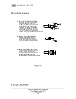
Page 27: ...THE JACKET 1 4 IN 2 PLACES 180 DEGREES APART TIN THE CENTER CONDUCTOR B SLIDE THE CONE ASSEMBLY UNDER THE BRAID UNTIL IT SOFT SOLDER THE CONTACT TO THE CENTER CONDUCTOR C SLIDE THE CLAMP NUT OVER THE FLARED PORTION OF THE CABLE THREAD THE CON NECTOR BODY ONTO THE NUT WHILE HOLDING THE NUT STATIONARY TIGHTEN SECURELY TOUCHES THE SHOULDER Figure 1 6 Drawing No 900422 INS8 INS 422 Installation Owners...

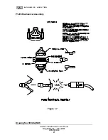
Page 28: ...A V I O N I C S L I M I T E D P1205 Mechanical Assembly Figure 1 7 Drawing No 900422 INS6 INS 422 Installation Owners Manual Original Issue June 2001 VPN 701034 27 ...

Page 29: ...Y AND INSTRUCTIONS Manual Title INS 422 INSTALLATION MANUAL Revision Original Issue 06 01 Part Number VPN 801004 Add delete or replace pages as indicated PAGE ACTION REMARKS INS 422 Installation Owners Manual Original Issue June 2001 VPN 701034 28 ...

Page 30: ...ified as Category X no test required Waterproofness 10 0 Equipment identified as Category X no test required Fluids Susceptibility 11 0 Equipment identified as Category X no test required Sand and Dust 12 0 Equipment identified as Category X no test required Fungus Resistance 13 0 Equipment identified as Category X no test required Salt Spray 14 0 Equipment identified as Category X no test require...

Page 31: ...ny manner and repair by other than the factory the repairs will be billed at costs In such cases an estimate will be submitted for approval before repair is initiated In most cases Val Avionics Ltd will provide a 48 hour turn around on its warranty and repair service We recommend that contact be made to the FACTORY CUSTOMER SERVICE DEPARTMENT prior to any unit return and obtain RETURN AUTHORIZATIO...

Reviews: