A V I O N I C S L I M I T E D
2.4.1
POST-INSTALLATION ADJUSTMENTS
The
INS 422
has been calibrated and adjusted at the factory. Additional
adjustments required by the installing agency (with specialized, precision test
equipment) to fine tune the Localizer and Glideslope display indications can
be accessed through the front panel as follows:
A. Localizer
Centering
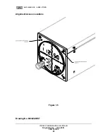
Remove top right mounting screw on front panel and with a small flat
blade screwdriver, turn R1283 left or right until only a center light
remains on the light bar. Replace mounting screw.
B. Glideslope
Centering
Remove top left mounting screw on front panel and with a small flat
blade screwdriver, turn R12004 left or right until only a center light
remains on the light bar. Replace mounting screw.
C.
VOR Balance
Access to the VOR Balance adjust pot (R412) is through a 1/8” hole on
the right side of the unit approximately 5-¾” from the front and 1”
from the top. Apply to the VOR/Localizer antenna port J610 a standard
VOR test signal at an RF level of –55 dBm and a bearing of 0 degrees
FROM. Using a small flat blade screwdriver, turn R412 left or right
until only the center light remains on the light bar.
INS 422 Installation/Owners Manual
Original Issue – June 2001
VPN 701034
14


