


A V I O N I C S L I M I T E D
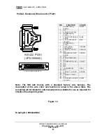
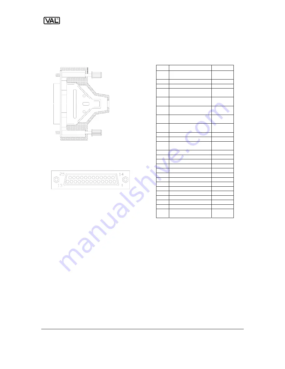
Pin Out, Function & Wire Color for P1201
P-1201 ( WIRING SIDE VIEW )
( VPN 550045 )
INS 422 P1201
Note: The INS 422 Comes with a standard factory wire harness. The
description of the wire color and function is listed in the above table. The
remaining pin terminals for external output are available for use as required for
interface to auto-pilot system.
PIN FUNCTION COLOR
1 GLIDESLOPE
(+
DOWN)
WHITE
2 NC
3 VOR/LOC
(+
FLAG)
4 GLIDESLOPE
(+
FLAG)
5 VOR/LOC
RECEIVER
AUDIO
BLUE
6
+ 13.75 VDC INPUT
(20 AWG)
RED
7 GLIDESLOPE
(-
FLAG)
8 AUTO-RADIAL
CENTERING
ORANGE
9 VOR/LOC
(+
LEFT) YELLOW
10 NC
11 MARKER
RECEIVE
AUDIO
GREEN
12 NC
13 FOR
FUTURE
USE
14 NC
15
GLIDESLOPE (+ UP)
VIOLET
16 NC
17 NC
18 NC
19 ILS
ENERGIZE
GRAY
20 NC
21 VOR/LOC
(+
RIGHT) BROWN
22 NC
23 VOR/LOC
(-
FLAG)
24 NC
25 AIRFRAME
GROUND
(20 AWG)
BLACK
Figure 1.3
Drawing No. 900422-INS4
INS 422 Installation/Owners Manual
Original Issue – June 2001
VPN 701034
23