


Chapter 7 _____________________________________________________________ Technical Data
VAISALA _______________________________________________________________________ 169
Connectors
QMT107
Pin numbers in Table 39 below refer to Figure 129 below.
Table 39
Cable wire connections
Connection Pin in Standard Cable
Signal
Color
Pin No
Connector L (CH2)
default in MAWS
GND
Blue
3
C
Low out
Black
4
L-
VCC
Brown
1
E
High out
White
2
H+
0106-035
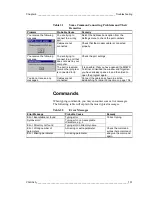
Figure 129
Connector of QMT107 (Viewed from Connecting
Side)
VCC is a power supply from 6 to 30 VDC, which draws a maximum
of 1.5 mA. This signal should be connected to the sensor excitation
pin of the data logger. GND is common ground for VCC.
Pins High out and Low out, provide differential measurement signals
from the probe. These signals should be connected to the data logger's
high impedance differential input (>1 M
Ω
).
Battery Charging
The QML102 data logger has an internal battery charger circuitry that
has a programmable charging voltage of 4.5 to 9.9 V and four
selectable current limits 100 mA, 300 mA, 500 mA, and 700 mA.
Charging voltage and charger input voltage (+ExtDC) can be
measured with 1 % accuracy and charging current can be measured


