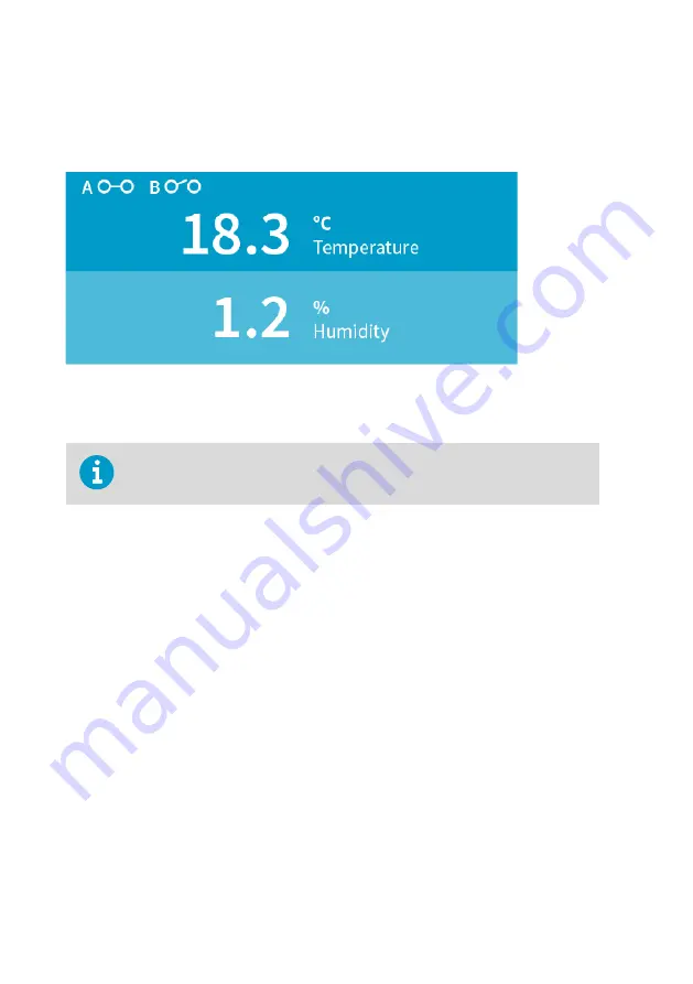
Relay state information
When one or both relays are enabled, the relay state (active/not active) is shown on the
transmitter display. You can also view the status of the relays with Insight PC software.
Figure 18 Relay icons on display (relay A active, relay B not active)
6.1.1 Relay activation options
Note that the values given must match the parameter and unit selections.
Relay activation and deactivation can be configured to happen either when the measurement
passes a single setpoint, or also when the measurement is within or outside a set range. The
following options are available:
• The relay activates when the measurement rises above or falls below a single setpoint,
and deactivates when the measurement returns to the other side of the setpoint value.
• When you set a higher value for
Activate above
and a lower value for
Activate below
, the
relay is
passive
when the measured value is in between the setpoints.
• When you set a lower value for
Activate above
than for
Activate below
, the relay is
active
when the measured value is in between the setpoints.
For examples of different relay activation options, see
Relay activation and hysteresis
.
Note that the hysteresis configuration has an effect on relay activation and deactivation. For
more information on hysteresis, see
. The effect of hysteresis is also
described in the examples in
Relay activation and hysteresis examples (page 35)
6.1.2 Relay hysteresis
If the measurement you are using to control the relay is likely to move back and forth close to
the activation setpoint, you can set a hysteresis that prevents the relay switching on and off
too frequently.
Indigo201 User Guide
M212842EN-B
34


