background image

Instructions for Use, Installation and Servicing ecoMAX pro

5

Sealed Components

Under no circumstances must the User interfere with any 

sealed component as this could result in a  

potentially dangerous situation arising.

Electrical Supply Failure

This boiler must be earthed.

The boiler will not work without an electrical supply.

Normal operation of the boiler should resume when the 

electrical supply is restored.

Reset any external controls to resume normal operation 

of the central heating.

If the boiler does not resume normal operation turn the 

mains reset switch off and on. If the boiler does not 

resume normal operation after this the overheat  

thermostat may have operated. The overheat  

thermostat would only operate under abnormal  

conditions and, under these circumstances; it would be 

advisable to consult your installation / servicing  

company.

2.10 Protection Against Freezing

The boiler has a built in frost protection programme as 

long as the electricity and gas are left switched on.

This device operates the burner and system pump when 

the temperature inside the boiler falls to 3°C.

Any other exposed areas of the system should be  

protected by a separate frost thermostat.

If the mains electricity and gas are to be turned off for 

any long periods during severe weather, it is  

recommended that the whole system, including the  

boiler, should be drained to avoid the risk of freezing. 

Make sure that, if fitted, the immersion heater in the 

cylinder is switched off. 

If you have a sealed water system contact your  

installation/ servicing company as draining, refilling and 

pressurising MUST be carried out by a competent  

person.

As a safety feature the boiler will stop working if the 

condensate drain becomes blocked. During freezing  

conditions this may be due to the forming of ice in the 

condense drain external to the house. Release an ice 

blockage by the use of warm cloths on the pipe. The 

boiler should then restart. Contact your installation/ 

servicing company if the fault persists.

2.11 Boilers Installed in a Compartment or Cupboard

If the boiler is fitted into a compartment or cupboard it 

does not require ventilation openings.

Do not use the compartment or cupboard for storage. 

2.12 Boiler Casing 

Do not remove or adjust the casing in any way, as  

incorrect-fitting may result in incorrect operation or  

failure to operate at all.

Important information 2

2.13 Condensate Drain

The condensate drain, see section 10.3, must not be 

modified or blocked.

2.14 Pluming from flue terminal

All condensing boilers produce a plume of water vapour 

from the flue terminal. This is due to the high efficiency 

and hence low flue gas temperature. This may increase 

in wet, damp weather but this is completely normal and 

indicates that the boiler is operating correctly.

2.15 Cleaning

This appliance contains metal parts and care should be 

taken when handling and cleaning with particular regard 

to edges. 

The boiler casing can be cleaned using a mild liquid 

detergent with a damp cloth, then a dry cloth to polish.

Do not use any form of abrasive or solvent cleaner as 

you may damage the paint work.

2.16 Maintenance and Servicing

For the continued efficient and safe operation of the  

boiler it is recommended that it is checked and serviced 

at regular intervals. The frequency of servicing will 

depend upon the installation conditions and usage, but in 

general, once a year should be enough.

If this appliance is installed in a rented property there is 

a duty of care imposed on the owner of the property by 

the current issue of the Gas Safety (Installation and Use) 

Regulations, Section 35.

Servicing/maintenance should be carried out by a  

competent person in accordance with the rules in force in 

the countries of destination.

To obtain service, please call your installer or Vaillant 

Service Solutions (0870 6060 777).

Please be advised that the installation engineer on 

completion of commissioning and servicing should 

complete the ‘Benchmark’ service record.

All CORGI Registered Installers carry a CORGI ID card, 

and have a registration number. Both should be recorded 

in your boiler Logbook. You can check your installer is 

CORGI registered by calling CORGI direct on: - 01256 

372300.

2.17 Guarantee

Vaillant provide a full parts and labour warranty for your 

appliance.

The appliance must be installed by a suitably competent 

person in accordance with the gas safety (installation 

and Use) Regulations 1998, and the manufacture's 

instructions. In the UK ‘CORGI’ registered installers 

undertake the work in compliance with safe and 

satisfactory standards.

Terms and conditions apply to the warranty, details of 

which can be found on the warranty registration card 

included with this appliance.

Failure to install and commission this appliance in 

compliance with the manufacture's instructions may 

invalidate the warranty (this does not affect your statutory 

rights).

Summary of Contents for ecoMAX pro 18E

Page 1: ...To be left with the user Instructions for Use Installation and Servicing ecoMAX pro Wall hung condensing boilers for traditional open vented systems GB 18 E 28 E...

Page 2: ...System unvented 13 6 9 Sealed water Systems 13 6 9 1 Safety Valve 14 6 9 2 Expansion Vessel 14 6 9 3 Pressure Gauge 14 6 9 4 Domestic Hot Water Cylinder 14 6 9 5 Water Make up 14 6 9 6 Filling a Seale...

Page 3: ...u will find a Benchmark gas boiler commissioning checklist It is very important that this is completed correctly at the time of installation commissioning and hand over to the user List of Content 1 I...

Page 4: ...rk on this appliance shows compliance with 1 Directive 90 396 EEC on the approximation of the laws of the Member States relating to appliances burning gaseous fuels 2 Directive 73 23 EEC on the harmon...

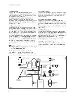
Page 5: ...e to operate at all Important information 2 2 13 Condensate Drain The condensate drain see section 10 3 must not be modified or blocked 2 14 Pluming from flue terminal All condensing boilers produce a...

Page 6: ...y The bar symbol is also shown and this indicates the modulating output of the boiler The boiler will automatically modulate to the output needed by the heating system the more bars that are displayed...

Page 7: ...s Installations the current Building Regulations and reference should be made to the current ETCI rules for Electrical Installation In GB the following Codes of Practice apply BS4814 BS6798 BS5440 Par...

Page 8: ...y G20 Gross CV s t 37 8 37 8 MJ m3 Maximum gas rate 2 00 3 02 M3 h Minimum gas rate 0 53 0 56 M3 h Burner CO2 Case on 9 0 0 2 9 0 0 2 Gas connection 15 mm Compression 15 mm Compression Water connectio...

Page 9: ...Instructions for Use Installation and Servicing ecoMAX pro 9 Fig 4 1 12729 12740 Fig 4 2 General information 4...

Page 10: ...fused 3 pin plug both to the current issue of BS 1363 may be used provided they are not used in a room containing a bath or shower The colours of three core flexible cable are blue neutral brown live...

Page 11: ...at least the minimum operational and servicing clearances are provided see fig 5 1 Additional clearances may be beneficial around the boiler for installation and servicing For flue installations where...

Page 12: ...le duty pump should be set to give a temperature difference of no greater than 20 C between the flow and return with the thermostat set at MAX which is about 80 C to give a flow rate as shown in table...

Page 13: ...tinel GE Betz Widnes Cheshire WA8 8UD Tel 0151 420 9595 6 6 Open Vented Water System The boiler must be supplied from an unrestricted water supply taken from a feed and expansion cistern situated at a...

Page 14: ...tem It shall be preset non adjustable with a lift pressure of 3 bar incorporating seating of a resilient material a test device and a connection for drain The safety valve discharge pipe must be route...

Page 15: ...lant appliances are certified only for use with genuine Vaillant flue pipes Only use genuine Vaillant flue pipes Malfunctions can occur if you use other accessories These may result in damage and inju...

Page 16: ...a fanned flue terminal should be positioned as follows a at least 2m from an opening in a building directly opposite and b so that the products of combustion are not directly directed to discharge acr...

Page 17: ...tional bends etc are detailed in the flue installation instructions Fig 8 1 13467 Installation preparation 8 Boiler fixing 9 Boiler fixing 9 1 Fitting the boiler hanging bracket If previously removed...

Page 18: ...a Preferably the drain pipe should run and terminate internally to the house soil and vent stack at least 450mm above the invert of the stack A trap giving a water seal of at least 75mm should be inco...

Page 19: ...current issue of BS1363 Do not interrupt the mains supply with a time switch or programmer Caution This appliance must be wired in accordance with these instructions Any fault arising from incorrect...

Page 20: ...water to the initial design pressure 12 3 Gas supply Isolate the boiler from the mains electrical supply The complete gas installation including the gas meter must be isolated tested for soundness and...

Page 21: ...e stabilisation time the boiler will ramp slowly to full rate rather than going immediately to full rate this feature is designed to cope with small system requirements 12 5 Testing Gas The boiler is...

Page 22: ...is recommended that it is checked and serviced at regular intervals The frequency of servicing will depend upon the installation conditions and usage but in general once a year should be adequate Draw...

Page 23: ...13 4 fully clockwise Turn the throttle back anti clockwise 5 1 2 turns Ensure that the gas analyser is set to the correct fuel setting Propane To obtain conversion follow the procedure as below Conne...

Page 24: ...2 with the B offset adjustment using a 2 mm allen key to 10 5 rotate clockwise to increase After checking the combustion press and hold the mode button for 10 seconds to return to the normal mode show...

Page 25: ...he flames are evenly covering the surface of the burner Inspect for signs of excessive flame lift or sooting 14 1 General To ensure the continued safe and efficient operation of the boiler it is recom...

Page 26: ...ce schedule in column 2 x 6 Remove the burner module as described in section 8 1 6 if maintenance schedule is required from steps 2 3 or 5 above Clean the primary heat exchanger Fit new burner door se...

Page 27: ...he reverse order to removal With the appliance operational carry out the following functional checks 1 Check the combustion preferably with a flue gas analyser see section 15 If a flue gas analyser is...

Page 28: ...t see fig 14 2 Remove the chassis front by pulling it out at the top from its retaining slots Note When replacing chassis front panel ensure the bottom fits behind lip Disconnect the gas valve electri...

Page 29: ...y to disengage the clip jaws from each other Remove flexible tubes from adapter Lift off the adapter Remove the drain connection downstream of the condense trap Remove the two condense trap securing s...

Page 30: ...e correct design pressure If the pressure is lower than this the vessel should be re pressurised using an air pump Refit the valve cap Re pressurise boiler and heating system Re commissioning the boil...

Page 31: ...turn up any room thermostats to call for demand With the boiler interface in normal operating mode press and hold the mode button for 10 seconds until a flashing 0 appears Press the key and scroll th...

Page 32: ...is on and a supply of 230V is present at the boiler terminal strip 3 Check that the gas supply to the boiler is on that it has been correctly purged and that an inlet pressure of 20mbar is available a...

Page 33: ...th NTC No function however if altered to 1 ON fault adjustable code 8 will be displayed tank NTC fault 10 Adaptive heating or night day switch No function adjustable 11 Night day setpoint Delta value...

Page 34: ...mer This would cause no pump overrun F16 Flame detection fault flame presence 5 s after burner stop Gas valve defective F17 Power supply 170 V Check electrical supply polarity Check fan F18 Local user...

Page 35: ...Instructions for Use Installation and Servicing ecoMAX pro 35 Fault finding wiring diagram 16 Fig 16 3 16 4 Fault Finding 12933...

Page 36: ...0260 Fan assembly 2 090750 Spark electrode 3 091258 Igniter unit 4 053574 Gas control valve 5 101771 Heating flow return NTC 2 6 101191 Overheat stat 7 130837 Main PCB 8 256271 Mains Reset Switch 9 13...

Page 37: ...Instructions for Use Installation and Servicing ecoMAX pro 37 Declaration of Conformity 17...

Page 38: ...Instructions for Use Installation and Servicing ecoMAX pro 38...

Page 39: ...Instructions for Use Installation and Servicing ecoMAX pro 39...

Page 40: ...0020005557_04 GB 08 2006 Subject to alteration...

Reviews: