


KBSL • KSL • KSLT
9
Montageanleitung
•
Mounting instructions
S
Beschädigungsgefahr für die
Stromabnehmer!
Die Anschlussleitungen dürfen
die Beweglichkeit des Strom-
abnehmers nicht behindern!
H
Schalter, Sicherungen und Ka-
bel zur Verdrahtung sind kun-
denseitig bereitzustellen und
zu montieren.
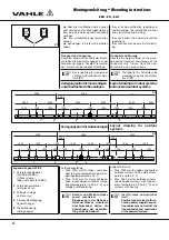
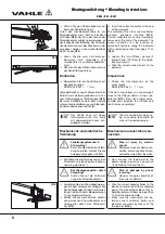
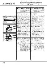
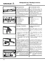
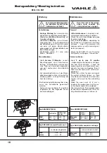
Kopfeinspeisung
Schlagen Sie Verstärkungsprofile (
1
)
auf die Kupferschienenenden der
Schleifleitung auf.
Treiben Sie den Anschlussbolzen (
2
)
bis zum Anschlag in die Kupferschie-
nen ein (
G17
).
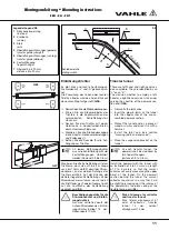
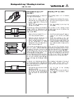
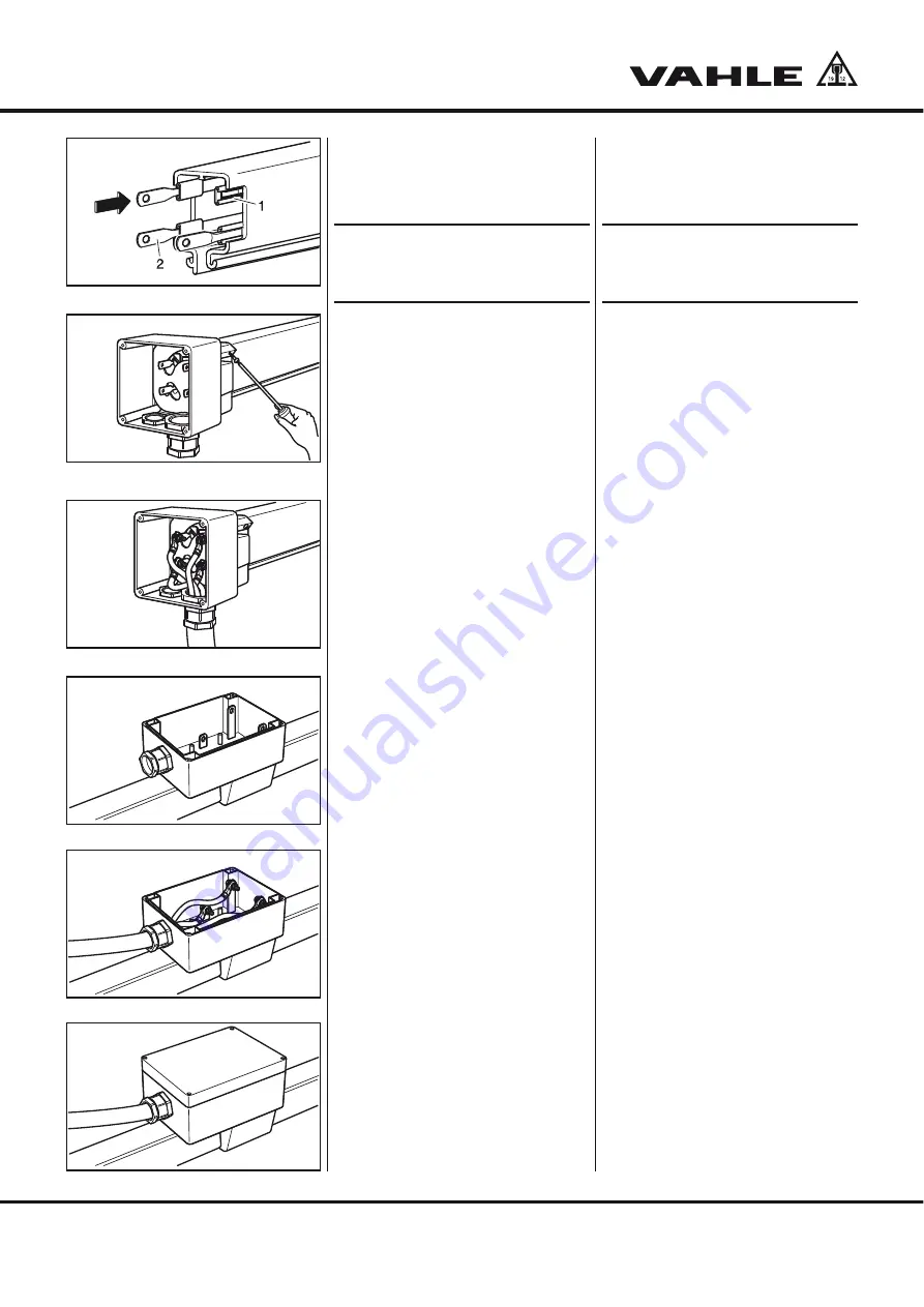
Montieren Sie die Leitungsverschrau-
bung M32, den Blindstopfen und die
zwei Bohrschrauben am Kasten vor.
Stecken Sie den Kasten auf das
Schleifleitungsende und fixieren Sie
ihn mit den zwei Schrauben (
G18
).
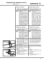
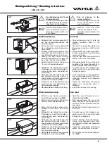
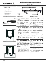
Setzen Sie die Anschlussleitung etwa
75 mm auf Einzeladerlänge ab.
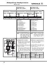
Bringen Sie die Kabelschuhe an den
Einzeladern an und führen Sie die An-
schlussleitung durch die Kabel-Ver-
schraubung.
Schrauben Sie die Kabelschuhe mit
den Sechskantschrauben (M5), Fä-
cherscheiben und Sechskantmuttern
an die Anschlussbolzen (
G19
).
Ziehen Sie die Kabel-Verschraubung
soweit an, bis eine Abdichtung zur
Anschlussleitung erfolgt.
Montieren Sie den Deckel mit Dichtung.
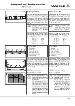
Streckeneinspeisung
Öffnen Sie den Deckel an der mon-
tierten Streckeneinspeisung (
G20
).
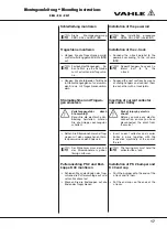
Setzen Sie die Anschlussleitung etwa
155 mm auf Einzeladerlänge ab.
Kürzen Sie die beiden vorderen Ein-
zeladern für L3 und L1 auf 90 mm
Länge.
Bringen Sie die Kabelschuhe an den
Einzeladern an und führen Sie die An-
schlussleitung durch die Kabel-Ver-
schraubung.
Schrauben Sie die Kabelschuhe mit
den Sechskantschrauben (M8), Fä-
cherscheiben und Sechskantmuttern
an die Anschlussfahnen (
G21
).
Ziehen Sie die Kabel-Verschraubung
soweit an, bis eine Abdichtung zur
Anschlussleitung erfolgt.
Setzen Sie den Deckel auf und verschlie-
ßen Sie den Anschlusskasten (
G22
).
S
Risk of damage to the
current collector!
The connecting cable may not
restrict the movement of the
current collector!
H
Switches, fuses and cable
used for the wiring shall be
provided and mounted by the
customer.
End feed
Drive reinforcing strips (
1
) onto the
copper conductor ends of the
powerail.
Hammer the connecting pin (
2
) into
the copper conductors until the limit
(
G17
).
Pre-assemble the cable gland M32,
the filler plug and the two self-drilling
screws on the box.
Plug the box onto the powerail end
and fix it with two screws (
G18
).
Strip approximately 75 mm of the outer
insulation of the connecting cable off so
that the individual wires are accessible.
Fix cable lugs on the individual con-
ductors and run the connecting cable
through the gland.
Fix the cable lugs to the connection
pins using hexagonal bolts (M5), ser-
rated lock washers and hexagonal
nuts (
G19
).
Tighten the cable gland until sealing
against the connecting cable is
achieved.
Install the box cover with sealing.
Line feed
Open the cover of the previously in-
stalled line feed (
G20
).
Strip approximately 155 mm of the
outer insulation of the connecting ca-
ble off so that the individual wires are
accessible.
Shorten the two front wires L3 and L1
to 90 mm.
Fix cable lugs on the individual con-
ductors and run the connecting cable
through the cable gland.
Fix the cable lugs to the line feed ter-
minals using hexagonal bolts (M8),
serrated lock washers and hexagonal
nuts (
G21
).
Tighten the cable gland until sealing
against the connection is achieved.
Put the cover on the terminal box and
fix it (
G22
).
G17
G18
G19
G20
G21
G22