
16
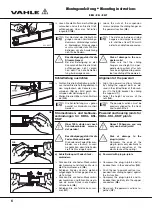
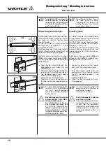
KTW-System mit
KBSL, KSL und KSLT
H
Kunststoff-Schleifleitung und
Tragschiene sowie Aufhänge-
winkel werden getrennt ver-
packt angeliefert und müssen
in der Reihenfolge Aufhänge-
winkel, Schleifleitung, Trag-
schiene montiert werden.
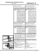
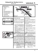
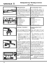
Aufhängewinkel montieren
Schrauben oder schweißen Sie die
Aufhängewinkel (
1
) an die vorhande-
ne Stahlkonstruktion (
S12
).
Der Aufhängeabstand sollte max. 2 m
betragen. Bei höheren Streckenlasten
(> 50 kg) 1 m Abstand.
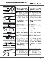
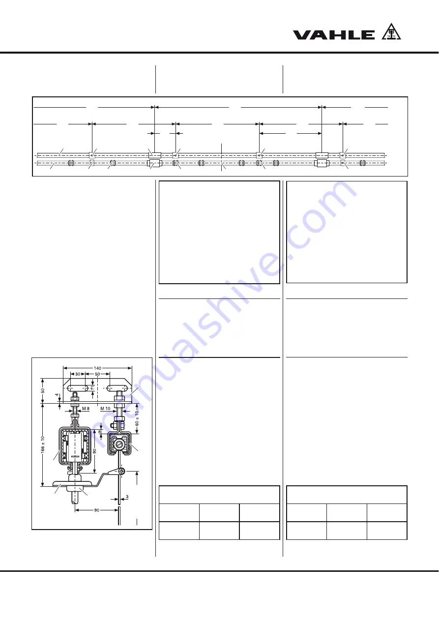
Richten Sie die Schleifleitung (
2
) und
die Tragschiene (
3
) in der Höhe so
aus, dass der Mitnehmer (
4)
des
Stromabnehmers (
5
) waagerecht liegt
(
S12
).
KTW-System with
KBSL, KSL and KSLT
H
Powerail, c-track and support
brackets are packed sepa
-
rately and shall be installed in
the following order: support
brackets, powerail, c-track.
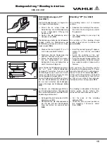
Installation of support brackets
Bolt or weld the support brackets (
1
)
to the steel structure (
S12
).
The distance between the supports shall
not exceed 2 m. With higher loads
(> 50 kg) 1 m distance.
Align powerail (
2
) and c-track (
3)
vertically so that the towing arm (
4
) of
the current collector trolley (
5
) as
-
sumes a horizontal position (
S12
).
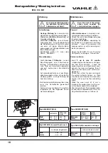
1
6
2
3
4
5
7
10
9
4
9
6
10
8
2000
2000
2000
4000 4000
2000
2000
1500
500
4000
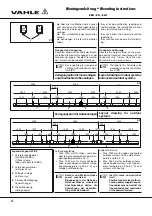
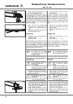
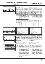
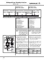
Legende S11
1
Schleifleitung
2
Verstärkungsklammer
3
Verbindungsmaterial
4
Festaufhängung
5
Mitte der Anlage
6
Gleitaufhängung
7
Tragschiene S2
8
Tragschienenverbinder
9
Festpunktaufhängung
10
Gleitaufhängung
Legende/Legend S11
1
powerail
2
stiffener clamb
3
joint pieces
4
fixpoint hanger
5
center of run
6
sliding hanger
7
c-track
8
c-track joints
9
fixpoint hanger
10
sliding hanger
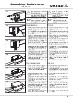
KTW-System mit
KBSL/
KSL/KSLT
KSLT mit
D + FP
Maß a
10
1
20
1
KTW-System with
KBSL/
KSL/KSLT
KSLT with
D + FP
Measure a
10
1
20
1
S11
1
3
5
4
2
S12
3 x 180 x 225 lg.
KBSL • KSL • KSLT
Montageanleitung
•
Mounting instructions