VAG Operation and Maintenance Instructions • 9
Warning:
Open the threaded plug part 11 only by 3
turns maximum. The pressure is relieved via the drai-
nage groove in the thread. Maintenance work must not
be performed before this has been done.
6.3 Maintenance work and replacement of
parts
Maintenance activities are:
• Cleaning
• Removing deposits
• Reapplying a coating of corrosion protection (when necessary)
• Gasket replacement (when necessary)
• Air release orifice replacement (when necessary)
Inspection should include examination of:
• Damage and corrosion
• Movability of the float in the shut-off device
• Tightness
• Function
• Nozzle bores free from obstruction
• Visible deposits on floats and guide components
For shaft installation the following additional inspections are
required:
• Proper condition and cleanliness of the shaft structure
• Working order of the intake and outlet air of the shaft as well
as drain
• Condition of measures for thermal insulation
• Condition of additional protective measures against infiltration
of dirt, microbes and rain water in the shaft
6.3.1 Design
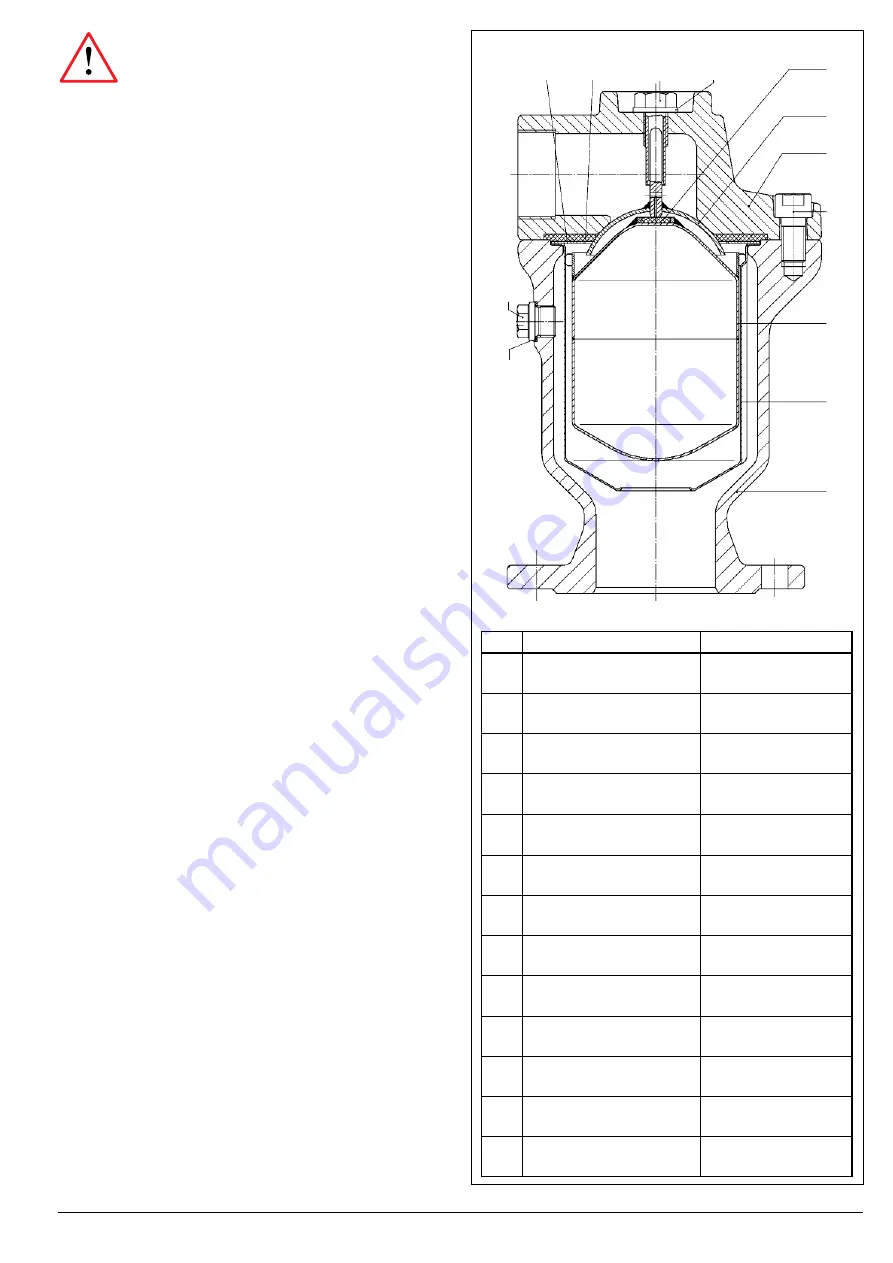
The design view in Picture 14 is a partial overview of the following
descriptions of the work procedures. Spare parts with associated
part numbers are available in our document VAG KAT-E 1912.
6.3.2 Recommendations for the replacement
of parts
All parts should be changed as needed. The interval is oriented
towards servicing requirements.
For the sealings (part 3.2 and 8) replacement is recommended
every 5 years.
Replace the sealing ring (part 12) each time you open the threa-
ded plug.
Picture 14: Design
Item Name
Material
1
Body
EN-JS 1030
2
Cover
EN-JS 1030
3.1
Float
DN 50 / PN 16 plastic
> DN 50 stainless steel 1.4571
3.2
Sealing
EPDM
4
Shell body
1.4541
5
Shut-off device
1.4541
6
Lead srew
1.4305
7
Supporting Disc
1.4541
8
8A
Flatsealing
Gasket p=0,1 - 1 bar
EPDM
9
Cylinder Head Screw
A4-70
10
Disc
A4
11
Plug Screw
A4
12
Sealing ring
Centellen
7
11
2
1
8/8A
6
10
3.2
5
9
3.1
12
4


