At the same time, check
“7.2.2 Aligning the System Disc“
.
7.2.2
Aligning the System Disc
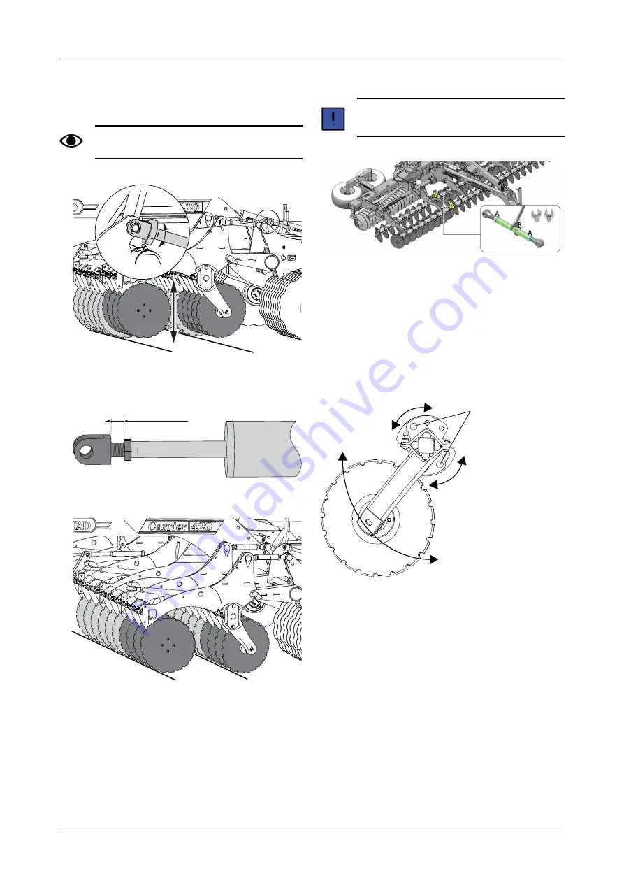
The piston rod may not be screwed out by more
than 20 mm from the lock nut
Figure 7.4
1. Release the lock nut on the hydraulic cylinder.
Figure 7.5
Figure 7.6
2. Adjust the Disc sections so that they align with the
other sections.
7.2.3
Adjusting the X-disc
If the X-disc is set incorrectly, there is a risk of a
ditch or a bank being formed.
Figure 7.7
Adjust the X-disc as follows:
1. Unfasten the counter-nuts (A).
2. Adjust the rigging screw (B) until an even result is
achieved.
3. Tighten the counter-nuts (A).
7.2.4
Adjusting the height of outer discs
Figure 7.8
To prevent the machine from leaving trailing lea lines, the
heights of the outer discs on each side can be individually
adjusted. Choose a setting that suits the working depth,
soil type, etc.
Adjust the height of the disc by undoing the nuts and
pulling out the bolts (A). Select a track position. Refit the
screws and nuts.
Max 20 mm
A
26
903815-en-gb; 23.09.2021


