BaseSTATION
Vaddio BaseSTATION - Document Number 342-0756 Rev A
Page 7 of 40
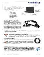
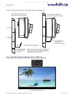
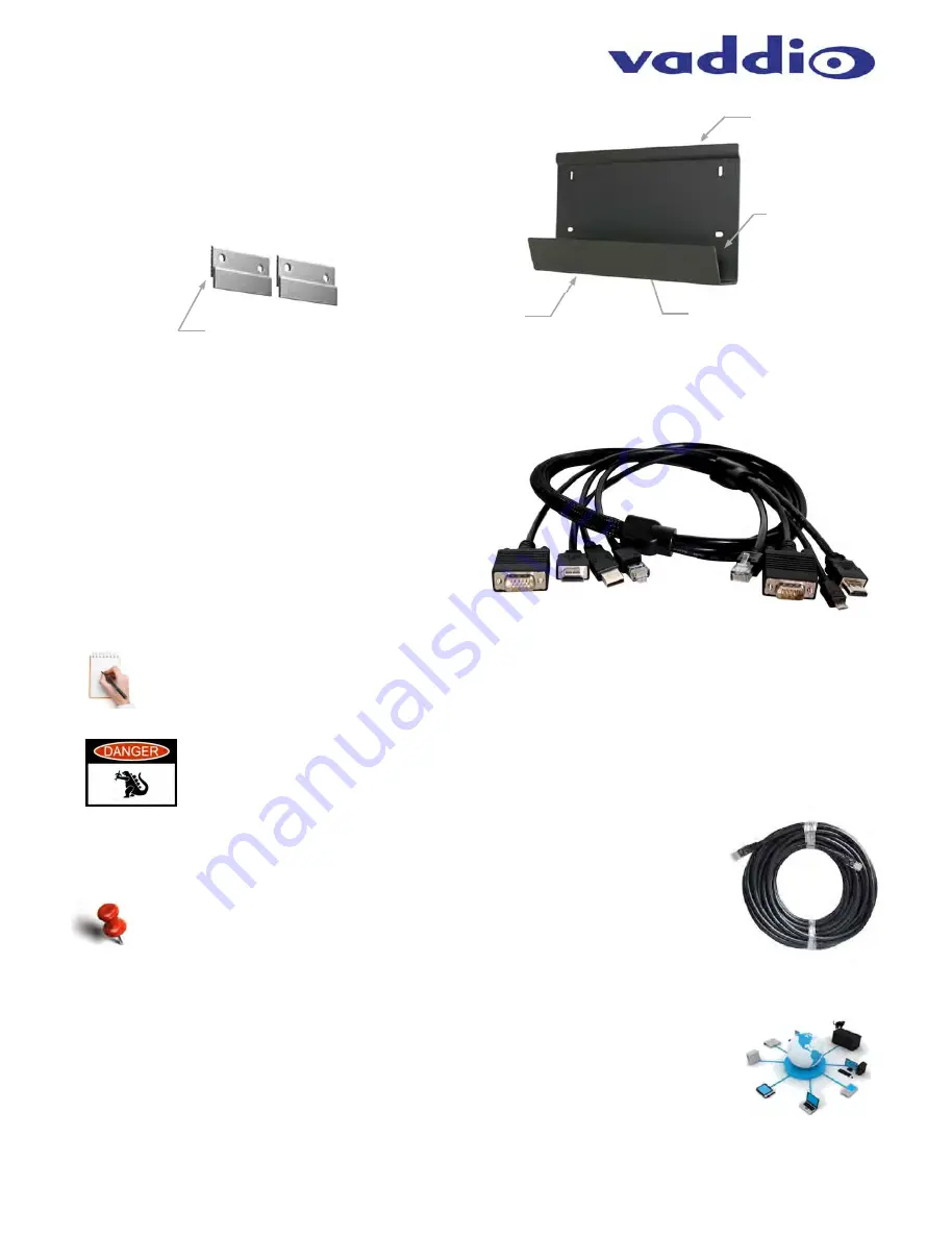
About the Premium Wall Mounting Kit (included)
One (1) Premium Wall Mount with integrated cable tray
One (1) Pair Z-clips attached to the back of the Camera Module
Four (4) 8-32 x 5/16” Phillips pan head screws for Z-clip
Six (6) Spiral Drywall Anchors
Six (6) #8 x 1.25” Screws for Wall Anchors
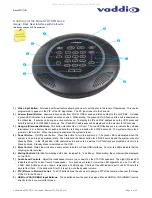
About the BaseSTATION,
HuddleSTATION or
GroupSTATION PC to Dock Interface Cable
Premium 3’ (.91m) 4x4 Interface Cable, extends the
USB 2.0, HDMI, VGA (RGBHV) and Network
connections out from the BaseSTATION Dock to the PC
used with UC software applications.
PC to Dock 4x4 Interface cable includes DE-15 for VGA
(RGBHV) male to male, USB 2.0 Type-A to Type-B
Micro, HDMI-M to HDMI-M and Ethernet 10/100
Network RJ-45 to RJ-45.
Note:
This 4x4 cable is an accessory to the BaseSTATION Deluxe System; however it is included with the
BaseSTATION Premier system.
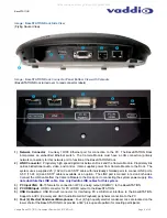
Another important note about the Cat-6 SSTP LINK Cable:
A 25’ (7.62 m) Cat-6 SSTP cable is supplied with the system and a 50’ (15.24 m) Cat-6 SSTP cable
is available as an accessory (see below). Due to the high speed communication between the
BaseSTATION Dock and Camera Module, please use only these two cabling options.
The Longer LINK Cable Option:
999-8903-000:
50’ (15.24m) Cat-6 SSTP Cable (26awg stranded, individually shielded pairs
with overall shield, gold contacts and metal shielded RJ-45 connector).
Note:
The system must be set with the internal web pages to use either the 25’
(7.62m) or the 50’ (15.24m) option. Please see the exciting and even stimulating
Screen Shot Tour included in this manual.
Installation Requirements
Please use qualified personnel for installation of the BaseSTATION system.
It is critical, even
imperative, that the IT professionals that install and maintain the network at the place of
BaseSTATION installation be involved with the provision of the network for the
BaseSTATION IP, VoIP and PC connectivity.
When calling for technical support, please
have the IT personnel involved with the installation available to put on the call.
Z-Clip Top
Channel
Integrated
Cable Tray
Two (2) 1.125” Cut-
outs for in-wall
cable management
(not shown)
2” x .75” Cutout
Bottom of Tray
Z-Clips Attach to the Back of
the Camera Module and hang
on the Z-Clip Top Channel on
the Wall Mount.
All manuals and user guides at all-guides.com


