BaseSTATION
Vaddio BaseSTATION - Document Number 342-0756 Rev A
Page 9 of 40
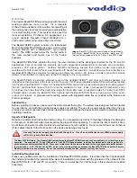
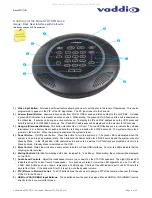
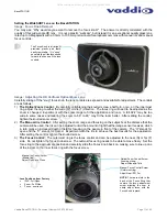
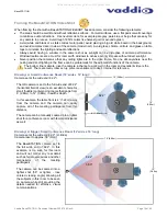
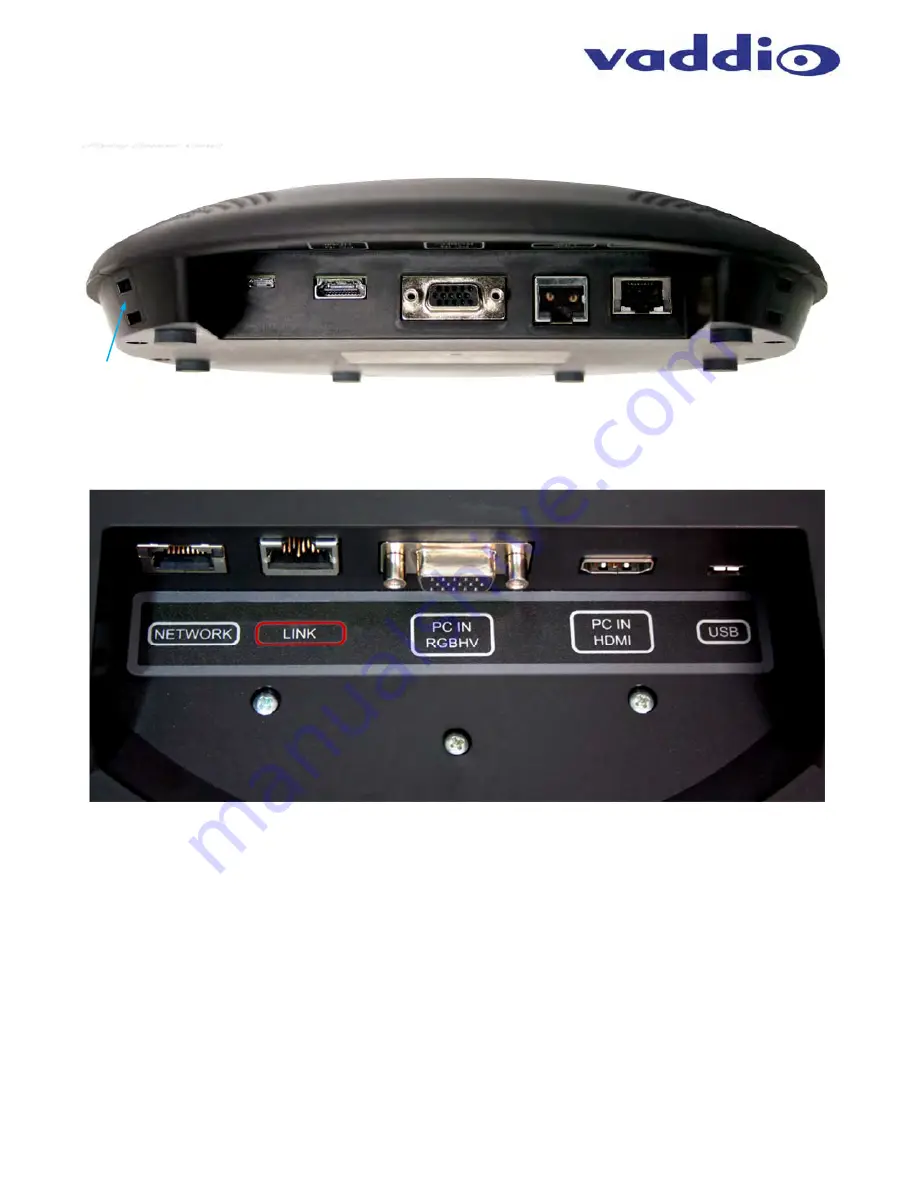
Image: BaseSTATION Dock Side View
(Flying Saucer View)
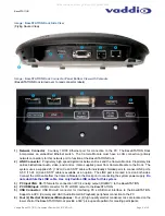
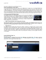
Image: BaseSTATION Dock Connector Panel Bottom View with Call-outs
(BaseSTATION Dock turned over to read connector labels)
1) Network
Connector
: Courtesy 10/100 Ethernet port for connection to the PC. The BaseSTATION Dock
incorporates an embedded Ethernet switch. The Camera Module must have a LAN connection (primary
network connection) for this network port to function at the BaseSTATION Dock.
2) LINK
Connector:
Proprietary high speed digital link between Dock and the Camera Module. Proprietary link
carries bidirectional audio, video, and control. It also supplies power from Camera Module to the Dock. The
system uses a supplied 25’ (7.62m) Cat-6 SSTP cable with individually shielded pairs to connect LINK ports.
A 50’ (15.24 m) Cat-6 SSTP cable is available as an option. The LINK port is marked in red on both sides.
Connect the LINK cable from the Camera Module to the Dock prior to connecting the system power supply.
Do
not substitute the LINK cable. Use only Vaddio LINK cables for this system.
3) PC Input VGA
: DE-15 female for connection of PC’s analog output (RGBHV): to the BaseSTATION.
4) PC HDMI Input:
HDMI connector for PC’s HDMI output to the BaseSTATION.
5) USB Connector:
USB Micro-B connector for interfacing PC’s USB Host interface to the BaseSTATION.
Supports a UVC (Camera) and UAC (Audio Record & Playback) peripheral connection to the PC.
6) Four (4) Electret Condenser Microphones:
Four (4) high quality electret condenser mics are located on the
lower shell of the BaseSTATION Dock provide a 360° pick-up audio pattern for meeting participants.
➊
➋
➌
➍
➊
➎
➍
➎
➋
➌
➏
All manuals and user guides at all-guides.com


