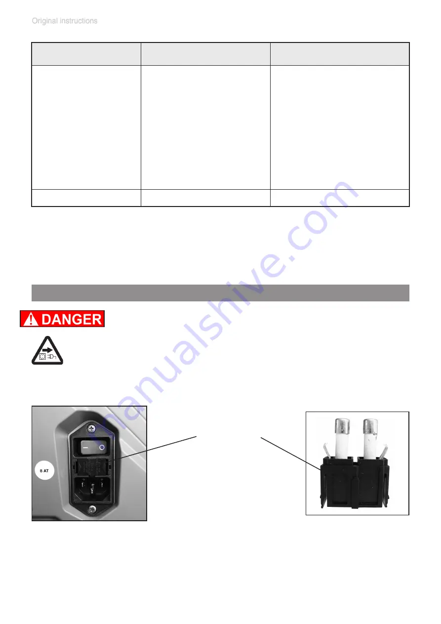
vacuubrand ME 16C NT-ME 16C NT+EK Instructions For Use Manual Download Page 46

page 46 of 88

fuse holder

 Keep the snap-fits squeezed and pull the fuse holder out.

 The fuse holder contains two fuses of the same type. Replace the 

defective fuse by a fuse of the same type (see “Technical data”, pg. 

24). 

 Insert the fuse holder into the housing until it snaps.

 Replacing the device fuse


Switch off the pump.


 Disconnect the electrical power cord

 before remov-

ing the fuse holder.

  Identify and eliminate the cause of failure before switch-

ing on the pump again.

 A service manual with exploded view drawings, spare parts list and 

directions for repair is available on request.

The service manual is intended for trained service people only.

Fault

Possible cause

Remedy

Pump too noisy.

Atmospheric or high 

pressure at the pump 

inlet?

Connect hose or silencer 

to pump outlet. Be careful 

not to cause outlet over-

pressure, especially with 

condensable vapors.

Diaphragm crack or 

diaphragm clamping 

disc loose?

Perform maintenance.

Other than above men-

tioned causes?

Contact local distributor.

Pump seized.

Contact local distributor.

Summary of Contents for ME 16C NT-ME 16C NT+EK

Page 1: ...Chemistry diaphragm pumps Chemistry vacuum systems ME 16C NT ME 16C NT EK MD 12C NT MD 12C NT EK MD 12C NT AK EK MV 10C NT MV 10C NT EK Instructions for use Technology for Vacuum Systems Original ins...

Page 2: ...d intensively including an endurance run of 14 hours Any faults even those which oc cur rarely are identified and can be eliminated immediately After completion of the endurance run every pump is test...

Page 3: ...L utilisateur ne doit mettre le dispositif en marche que s il comprend le mode d emploi pr sent ou si une traduction compl te et correcte du mode d emploi est sous ses yeux Le dis positif ne doit pas...

Page 4: ...lmistelut ja muut toimenpiteet Vakuumilaitteen turvallisuustiedot GR HR Pa nja ove upute ne postoje na svim jezicima Europske Unije Korisnik nemora raditi sa apara tom ako ne razumije ove upute U tom...

Page 5: ...Bij gebruik van deze apparatuur is het noodzakelijk een technisch correcte vertaling van de complete gebruiksaanwijzing te hebben Voor het in gebruik nemen van het apparaat moet de gebruiksaanwijzing...

Page 6: ...orabnik ne sme upravljati z napravo e ne razume teh navodil V primeru nerazumljivosti mora biti na voljo tehni no pravilen prevod Navodila se morajo prebrati in razumeti pred uporaba naprave opravljen...

Page 7: ...Wetted parts 27 Abbreviations 28 Pump parts 28 Use and operation 31 Installation 31 Vacuum connection inlet 32 Separator AK at the inlet 33 Connecting the outlet 34 Exhaust waste vapor condenser EK a...

Page 8: ...the pump housing 71 Replacing the overpressure safety relief device 78 Repair Maintenance Return Calibration 81 Warranty 82 Health and safety clearance form 83 EC Declaration of Conformity of the Mac...

Page 9: ...om the pump and the pumped substances VACUUBRAND disclaims any liability for inappropri ate use of these pumps and for damage from failure to follow instructions contained in this manual This manual i...

Page 10: ...s must not be disposed of in the domestic waste at the end of their service life Used electronic devices contain harmful substances that can cause damage to the environment or human health End users a...

Page 11: ...lace the protective caps if the equipment is not used immediately Store the equipment in dry and non corrosive conditions see also Technical data pg 24 Do not use any damaged equipment Use the handles...

Page 12: ...tant to the pumped substances prior to operation Use the equipment only as intended that is for genera tion of vacuum in vessels designed for that purpose Any other use will automatically invalidate a...

Page 13: ...fferences between inlet and outlet See sec tion Technical data pg 24 Do not operate the pump with overpressure at the inlet Avoid overpressure of more than 17 5 psi absolute 1 2 bar absolute in the ev...

Page 14: ...outlet of the pump with an inner diameter at least as large as the diameter of the pump s tubing to avoid overpressure at the outlet and reduction of pumping speed at the inlet Allow the equipment to...

Page 15: ...pment can be operated safely see also IP degree of protection Technical data pg 24 Operating conditions These pumps are not approved for operation in po tentially explosive atmospheres Do not operate...

Page 16: ...even to the point of exceeding the maximum permitted temperatures Check the inlet and outlet of the pump if there is a danger of forming deposits inside the pump e g in the pump chambers the pump cham...

Page 17: ...n tially explosive mixtures at the outlet of the pump or dilute them to non explosive concentrations Never operate this pump if it has a damaged cord or plug If the pump is not working properly has be...

Page 18: ...table measures to prevent contamination of the pumped substances or the environment Ensure that no parts of your clothing hair or fingers can be caught or drawn in at the inlet of the pump Never inser...

Page 19: ...ate protective measures to allow for the possibility of failure and malfunction The protective mea sures must also allow for the requirements of the respec tive application A temperature sensor in the...

Page 20: ...t five seconds before starting maintenance to allow the capacitors to discharge Note The pump may be contaminated with process chemicals which have been pumped during operation Ensure that the pump is...

Page 21: ...p Interventions on the device Work on the equipment may be performed only by a qualified person Work on electrical equipment in particular may be per formed only by qualified electricians Ensure that...

Page 22: ...ed by gases vapors or mists normally don t occur or if they do occur are likely to do so only infrequently and for a short period only Equipment in this category ensures the requisite level of protect...

Page 23: ...s or Techni cal data After any intervention at the equipment e g repair maintenance the ul timate vacuum of the pump has to be checked Only if the pump achieves its specified ultimate vacuum is the pu...

Page 24: ...temperature storage operation F C 14 to 140 50 to 104 10 to 60 10 to 40 Permissible relative atmospheric moisture during operation no condensation 30 to 85 Maximum permissible installation altitude ab...

Page 25: ...aste vapor condenser EK psi bar 87 absolute 6 absolute Permissible range of coolant tempera ture waste vapor condenser only EK F C 5 to 68 15 to 20 Volume of catchpot only AK EK quarts ml 0 52 500 Typ...

Page 26: ...essure level uncertainty KpA 3 dB A dB A 50 Weight approx 100 120 V version EK AK EK 200 230 V version EK AK EK lbs kg lbs kg lbs kg lbs kg lbs kg lbs kg 60 4 27 4 62 6 28 4 63 9 29 0 60 2 27 3 62 4 2...

Page 27: ...orced Diaphragm PTFE Valves ME 16C NT PTFE Valves MD 12C NT MV 10C NT FFKM O rings FPM Valve head ECTFE carbon fiber reinforced Tubing PTFE Fittings ETFE ECTFE Gas ballast tube PTFE carbon reinforced...

Page 28: ...re safety rellief device 14 Coolant inlet 15 Coolant outlet Pump parts Abbreviations ECTFE Ethylene Chlorotrifluoroethylene ETFE Ethylene Tetrafluoroethylene FEP Perfluoroethylene perfluoropropylene c...

Page 29: ...page 29 of 88 ME 16C NT MD 12C NT MV 10C NT 1 5 3 2 6 4 8 7 9...

Page 30: ...page 30 of 88 ME 16C NT EK MD 12C NT EK MV 10C NT EK MD 12C NT AK EK 9 9 8 8 10 11 14 12 13 15 1 2 10 14 13 15 2 12 1...

Page 31: ...niowych Informa o de Seguran a para Equipamento que funciona a V cuo Instruc iuni de siguran pentru aparatele de vidare S kerhetsinformation f r vakuumutrustning Varnostni nasveti za vakuumske naprave...

Page 32: ...to connect a vacuum hose caoutchouc 15 mm ID see Accesso ries Spare parts pg 43 if necessary inlet Use connecting hoses with large diameter and keep them as short as possible to avoid flow losses Loca...

Page 33: ...of the pump especially if the gas ballast valve is open If this constitutes a potential source of danger take appropri ate safety measures When assembling ensure vacuum tightness After as sembly check...

Page 34: ...e g into a fume hood Never block the gas outlet The exhaust line must always be free of obstructions no back pressure to ensure an unimpeded discharge of gas The cross section of the outlet tubing mus...

Page 35: ...hattering in case of break age or implosion Assemble the catchpot at the exhaust waste vapor condenser using a joint clip over pressure safety relief device Check the overpressure safety relief device...

Page 36: ...ge Only install the optional coolant valve in the supply line of the exhaust waste vapor con denser Note Install the hoses of the cooling system in a way to avoid the flow dripping of con densed water...

Page 37: ...pump on O I Electrical connection During operation Vent and dispose of potentially dangerous gases or vapors at the outlet of the pump appropriately Due to the high compression ratio the pump might ge...

Page 38: ...p if the pressure difference between inlet and outlet ports exceeds max 16 0 psi 1 1 bar Attempts to start the pump at higher pressure difference may cause stalling and damage of the motor NOTICE If p...

Page 39: ...ating e g due to hot process gases Maximum permissible temperature range see Gas inlet temperatures pg 27 Make sure the fan s air supply is adequate Do not place the pump on soft surfaces e g rub ber...

Page 40: ...as To reduce condensation in the pump do not pump vapor before the pump has reached its operating temperature Open the gas ballast valve when pumping condensable vapors Turn gas ballast cap to open va...

Page 41: ...s at approximately 80 of the total filling level to avoid problems when removing the catchpots Removing the catchpots Catchpot at outlet Remove joint clip Remove catchpot and drain condensate Catchpot...

Page 42: ...een exposed to conden sate Allow the pump to continue to run at atmo spheric pressure for a few minutes Has the pump been exposed to media which may damage the pump materials or form deposits Check an...

Page 43: ...e DCP 3000 with gauge head VSK 3000 20683170 100 230 V 50 60 Hz Exhaust waste vapor condenser with catchpot 0 52 qt 500 ml 20699948 Upgrade kit including holder and front cover Separator inlet 2069997...

Page 44: ...UBRAND for details VACUU LAN manual flow control module VCL 01 20677106 VACUU LAN shut off manual flow control module VCL 02 20677107 VACUU LAN automatic control module VCL B 10 20677208 VACUU LAN man...

Page 45: ...low motor to cool down identify and eliminate cause of failure Manual reset is necessary Switch off pump or unplug Pump does not achieve its ultimate vacuum or usual pumping speed Centring ring at sma...

Page 46: ...he cause of failure before switch ing on the pump again A service manual with exploded view drawings spare parts list and directions for repair is available on request The service manual is intended f...

Page 47: ...with the pro cess chemicals that have been pumped during opera tion Ensure that the pump is decontaminated before maintenance Avoid the release of pollutants Never operate a defective or damaged pump...

Page 48: ...system is maintenance free In demanding circumstances it may be efficient to check and clean the pump heads on a regular basis In normal use the lifetime of the diaphragms and valves is typically 15...

Page 49: ...page 49 of 88 Disassembling the pump housing 1 3 2...

Page 50: ...page 50 of 88 4 6 5 1 2 4 4x 2 5 mm 2 5 mm...

Page 51: ...page 51 of 88 7 9 8 4 4x without EK...

Page 52: ...page 52 of 88 10 12 11 4 2x 4 4x Don t loosen this screw...

Page 53: ...page 53 of 88 13 15 14 5 2x 5 2x...

Page 54: ...page 54 of 88 16 18 17 2 5 mm...

Page 55: ...osition Component 1 Clamping bracket 2 Disc spring 3 Valve head 4 O rings 5 Valves 6 Head cover 7 Diaphragm clamping disc with square head screw 8 Diaphragm Position Component 9 Diaphragm support disc...

Page 56: ...page 56 of 88 Replacing the diaphragms 19 21 20 Clean 5 8x 20696867 20696839...

Page 57: ...page 57 of 88 22 24 23 1 2 3 Pay attention to number of washers...

Page 58: ...page 58 of 88 25 27 26...

Page 59: ...page 59 of 88 28 30 29 1 2 Pay attention to number of washers 4 4 ft lbf 6 Nm It is recommended to use a torque wrench Attach torque wrench to diaphragm key hexagonal bolt 6 mm wide...

Page 60: ...page 60 of 88 33 32 31 5 8x Screw in diagonally at first slightly then tighten 8 9 ft lbf 12 Nm T20 4x Replacing the valves...

Page 61: ...page 61 of 88 34 36 35 Clean 20696867 20696839...

Page 62: ...page 62 of 88 37 39 38 IN IN EX EX 4x...

Page 63: ...page 63 of 88 40 42 41 IN EX T20 4x 2 2 ft lbf 3 Nm...

Page 64: ...page 64 of 88 43 45A 44 Maintain all pump heads in the same way MD 12C NT...

Page 65: ...page 65 of 88 45B 45C 45D ME 16C NT MV 10C NT ME 16C NT MD 12C NT MV 10C NT...

Page 66: ...page 66 of 88 Replacing the valve at the distributor only MD 12C NT MV 10C NT 1 2 5 mm 1A 2 5 mm without EK 1B without EK size 2 2x...

Page 67: ...page 67 of 88 4A 3 2 size 2 2x Version A valve 24 4 mm...

Page 68: ...page 68 of 88 5A 20696839 24 4 mm 26 mm 4B 5B 20696839 37 mm 40 mm Version B valve 37 mm...

Page 69: ...page 69 of 88 6 7 size 2 2x 7A without EK size 2 2x...

Page 70: ...page 70 of 88 9 8 Do not operate the pump without pump housing Danger due to freely rotating fan Risk of overheating due to missing cooling air guide...

Page 71: ...page 71 of 88 Assembling the pump housing 46 47 48 5 2x 8 9 ft lbf 12 Nm...

Page 72: ...page 72 of 88 50 49 5 2x 8 9 ft lbf 12 Nm 51...

Page 73: ...page 73 of 88 53 52 4 4x 3 7 ft lbf 5 Nm 54 4 2x 3 7 ft lbf 5 Nm...

Page 74: ...page 74 of 88 56 55 4 4x 3 7 ft lbf 5 Nm 57...

Page 75: ...page 75 of 88 59 58 60 4 4x 3 7 ft lbf 5 Nm...

Page 76: ...page 76 of 88 62 61 63...

Page 77: ...ecified ultimate vacuum is not achieved and if this does not change after the break in period Check hose connectors at pump heads for leaks If necessary recheck valve seats and pump chambers Checking...

Page 78: ...page 78 of 88 Replacing the overpressure safety relief device at the exhaust waste vapor condenser 3 2 1 T20 4x size 1 4x...

Page 79: ...page 79 of 88 4 20638821 20638821 5 6...

Page 80: ...page 80 of 88 7 T20 4x size 1 4x 8...

Page 81: ...itions apply to on site work No repair maintenance return or calibration is possible unless the correctly completed health and safety clearance form is returned Devices sent are rejected if applicable...

Page 82: ...ments Particular care must be taken with components and waste oil which have been contaminated with dangerous substances from your processes Do not incinerate fluoroelastomer seals and O rings You may...

Page 83: ...page 83 of 88 Declarations and certificates...

Page 84: ...page 84 of 88...

Page 85: ...se Period EFUP EFUP defines the period in years during which the hazardous substances contained in electrical and electronic products will not leak or mutate under normal operating conditions During n...

Page 86: ...the above table the subassemblies are not intentionally manufactured or formulated with lead Pb mercury Hg cadmium Cd hexavalent chromium Cr VI polybrominated biphenyls PBB and polybrominated dipheny...

Page 87: ...page 87 of 88...

Page 88: ...theim 97877 Wertheim GERMANY GERMANY Phone Head office 49 9342 808 0 Sales 49 9342 808 5550 Service 49 9342 808 5660 Fax 49 9342 808 5555 Email info vacuubrand com Web www vacuubrand com Version 20901...

Reviews: