


32 • vacon
cabling and connections
Tel. +358 (0)201 2121 • Fax: +358 (0)201 2121 205
6
5
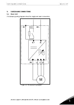
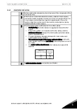
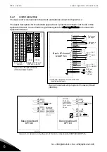
Connect the cables:
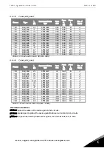
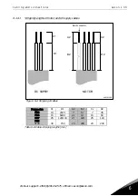
Strip the motor and DC supply cables as advised in Figure 6-2
and Table 6-6.
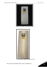
Remove the screws of the cable protection plate. Do not open the
cover of the power unit!
Make holes into and pass the cables through the rubber
grommets on the bottom of the power unit. The rubber grommets
are delivered in a separate bag.
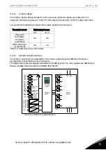
Connect the DC supply, motor and control cables into their
respective terminals.
For information on the installation of greater units, please contact
the factory or your local distributor.
For Information on cable installation according to UL
regulations, see Chapter 6.1.3.
For information on cable installation according to EMC
regulations, see Chapter 6.1.3.
Make sure that the control cable wires do not come in contact with
the electronic components of the unit.
If an external brake resistor (optional) is used, connect its cable
to the appropriate terminal.
Check the connection of the earth cable to the motor and the
inverter terminals marked with
.
Connect the separate shield of the power cable to the earth
terminals of the inverter, motor and the supply centre.
Attach the cable protection plate with the screws.
Ensure that the control cables or the cables of the unit are not
trapped between the frame and the protection plate.
Summary of Contents for FI4
Page 1: ...vacon nxi inverters fi4 fi8 user manual ...
Page 2: ......


