


28 • vacon
cabling and connections
Tel. +358 (0)201 2121 • Fax: +358 (0)201 2121 205
6
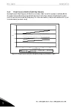
6.1.1
Power connections
6.1.1.1
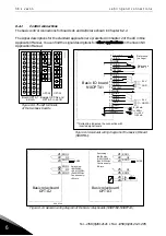
DC supply and motor cables
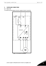
The power cables are connected to terminals DC+ and DC- (R+/B+ and DC terminals when using an
external charging circuit) and the motor cables to terminals U, V and W. A cable entry gland should
be used at the motor cable end to reach the EMC levels, see Table 6-1.
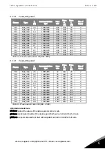
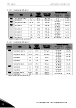
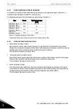
Use cables with a heat resistance of at least +60C. The cables and the fuses must be sized according
to the inverter nominal output current which you can find on the rating plate. Installation of cables
according to UL regulations is presented in Chapter 6.1.3 and aR fuse sizes in Tables 6-2 and 6-3.
The minimum dimensions of the Cu-cables are shown in Table 6-4.
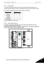
If the motor temperature protection of the drive (see Vacon All in One Application Manual) is used as
an overload protection, the cable shall be chosen accordingly. If three or more cables are used in
parallel for bigger units, each cable requires a separate overload protection.
These instructions apply only to installations with one motor and one cable connection from the
inverter to the motor. In any other case, ask the factory for more information.
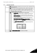
Cable type
Level T
Supply cable
Power cable intended for fixed installation and the specific DC
voltage. Shielded cable not required. (NKCABLES/MCMK or
similar recommended)
Motor cable
Power cable equipped with concentric protection wire and
intended for the specific mains voltage. (NKCABLES/MCMK or
similar recommended).
Control cable
Screened cable equipped with compact low-impedance shield
(NKCABLES/jamak, SAB/ÖZCuY-O or similar).
Table 6-1. Cable types required to meet standards
6.1.1.2
Control cable
For information on control cables, see Chapter 6.2.1.1 and Table 6-1.
Summary of Contents for FI4
Page 1: ...vacon nxi inverters fi4 fi8 user manual ...
Page 2: ......


