background image

E

N

G

L

IS

H

38

5 - CONTROL PANEL

5.1 - DISPLAY

When power is on, the control unit checks that display correctly
operates by switching on all segments for 1.5 sec. 

8.8.8.8

.

Firmware version, e.g. 

Pr I.2

, will be viewed in the following 

1.5 sec. 

Panel will be viewed upon completion of this test.

PLEASE NOTE: if the panel is off, the control unit should be
in ENERGY SAVING mode; press the OK key to turn it on.

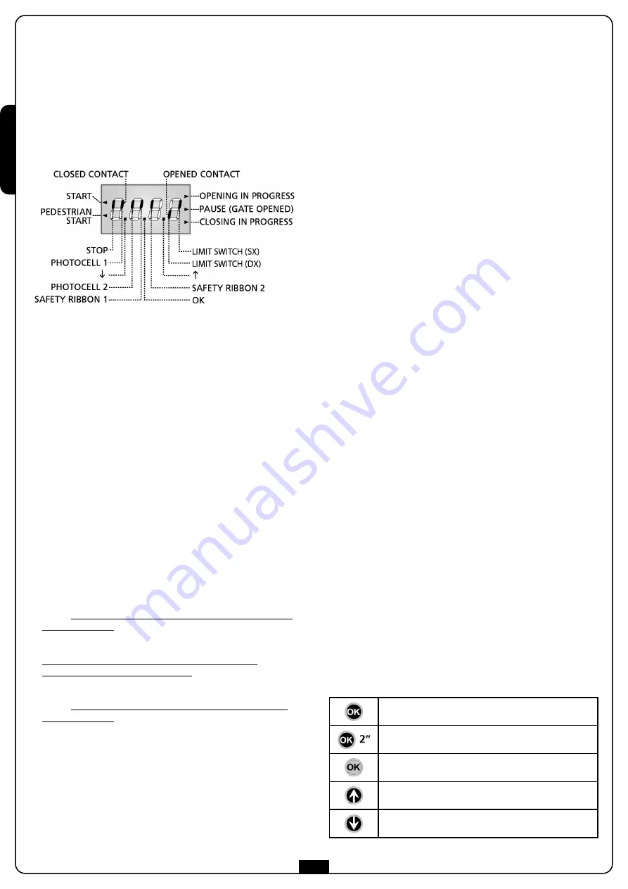
The control panel represents the physical status of the
terminal board contacts and of the program mode keys: if the
upper vertical segment is on, the contact is closed; if the lower
vertical segment is on, the contact is open (the above picture
shows an instance where the inputs PHOTO1, PHOTO2, EDGE1,
EDGE2 and STOP have all been correctly connected).

NOTE: if you are using an ADI module, other segments may
appear on the display, see the paragraph dedicated to the
“ADI INTERFACE”

Points being among display digits show the status of
programming push-buttons: as soon as a push-button is pressed,
its relevant point turns on.

The arrows on the left of the display show the state of the start
inputs. The arrows light when the related input is closed.

The arrows on the display right side show the gate status:

• The highest arrow turns on when the gate is into its opening

phase. If it blinks, it means that the opening has been caused
by a safety device (border or obstacle detector).

• The central arrow shows that the gate is on pause.

If it blinks, it means that the time countdown for the
automatic closing has been activated.

• The lowest arrow blinks when the gate is into its closing 

phase. If it blinks, it means that the closing has been caused
by a safety device (border or obstacle detector).

5.2 - USE OF THE KEYS FOR PROGRAMMING

The control unit functions and times are programmed by means
of a special configuration menu, which can be accessed and
explored by using the 3 keys, 

h

i

and 

OK

, located on the side of

the control unit display.

PLEASE NOTE: Outside the configuration menu, pressing
the 

h

key activates the START command, pressing the 

i

key

activates the PEDESTRIAN START command.

There are the following three kinds of menu items:
• Function menu
• Time menu
• Value menu

Function menu setup

Function menus allow selecting a function from among a group
of available options. When you enter into a function menu, the
current active option will be viewed; you can scroll all available
options through 

i

and 

h

keys. By pressing the 

OK

key, you will

activate the option viewed and you will return to the
configuration menu.

Time menu setup

Time menus allow setting a function duration. When you enter
into a time menu, the current setup value will be viewed; the
display mode depends on the current value:

Each time you press 

h

key, current time value increases and each

time you press the 

i

key, current time value decreases.

By holding down the 

h

key, you can quickly increase the time

value, up to reach the max. value allowed for this item. Vice
versa, by holding down the 

i

key, you can quickly decrease

the time value down to reach 

0.0”

In some circumstances, setting the value to 0 means that the
relevant function is disabled, in this case, ‘no’ will appear instead
of 

0.0”

By pressing on 

OK

you will confirm the displayed value and

you will return to the configuration menu.

Value menu setup

Value menus are similar to time menus; however, the setup value
can be any number.
By holding down 

h

or 

i

keys, the value will increase or

decrease slowly.
By pressing on 

OK

you will confirm the displayed value and

you will return to the configuration menu.

The main programming menus of the control unit are shown in
the next pages.
To go through the menus use the three keys “

h

i

and 

OK

according to the following chart:

Press and release the push-button 

OK

Keep pressed the push-button 

OK

for 2 seconds

Release the push-button 

OK

Press and release the push-button 

h

Press and release the push-button 

i

Summary of Contents for ALFARISS

Page 1: ...EUR ELECTROMECANIQUE 24V IRREVERSIBLE A CREMAILLERE POUR PORTAILS COULISSANTS JUSQU A 300 KG DE POIDS MOTOR ELECTROMECANICO 24V IRREVERSIBLES A CREMALLERA PARA PUERTAS CORREDERAS HASTA 300 KG DE PESO...

Page 2: ......

Page 3: ...34 4 2 ACTIVATION INPUTS 34 4 3 STOP 35 4 4 CONNECTING PHOTOCELLS 35 4 5 CONNECTING SAFETY RIBBONS 35 4 6 EXTERNAL AERIAL 36 4 7 LOW VOLTAGE LIGHT OUTPUT 36 4 8 COURTESY LIGHTS 36 4 9 POWER SUPPLY 36...

Page 4: ...y and hazard warnings on the machinery and equipment should be complied with Electromechanical actuators for gates are not intended to be used by people including children with diminished physical sen...

Page 5: ...t person The risk analysis should take into consideration all danger zones for the automation device which should be appropriately protected and marked In a clearly visible area apply a sign with info...

Page 6: ...50 Idling current A 0 9 Full load current A 3 Gate maximum speed m s 0 18 Maximum thrust N 330 Duty cycle 50 Pinion M4 Z16 Working temperature C 20 55 Motor weight Kg 7 5 Protection degree IP 44 Maxim...

Page 7: ...and parallel to the gate 5 Wait for the complete setting of the concrete 6 Unscrew the bolts fixing the base to the clamps and put the motor on the plate 7 Insert the 4 grains with their nuts in the p...

Page 8: ...gate making sure that they stand at the same height than the motor pinion The rack MUST BE positioned 1 or 2 mm over the pinion of the motor all the gate length 3 4 INSTALLING THE MAGNETIC LIMIT SWITC...

Page 9: ...restore the automation proceed as follows 1 Turn the key L anticlockwise until reached the limit switch then draw it out 2 Turn the key K anticlockwise closing the hatch of the lock then draw it out...

Page 10: ...rse the connectors 4 2 ACTIVATION INPUTS PD13 control unit is equipped with two activation inputs START and START P whose operation depends on the programmed operation modes see Strtitem of programmin...

Page 11: ...control unit Use outputs having normally closed contact mSAFETY RIBBONS INSTRUCTIONS If several edges with normally closed contacts are used the outputs should be connected in series If several conduc...

Page 12: ...VER PD13 control unit is suitable for plugging in a MRx receiver having a high sensitivity super heterodyne architecture MRx module receiver is provided with 4 channels and each of them is suitable fo...

Page 13: ...ing traditional devices with N O contact J2 Pedestrian open command for connecting traditional devices with N O contact J3 STOP command N C contact J4 Common J5 Photocell 1 xterior N C contact J6 Phot...

Page 14: ...explored by using the 3 keys h i and OK located on the side of the control unit display PLEASE NOTE Outside the configuration menu pressing the h key activates the START command pressing the i key ac...

Page 15: ...ges which will get lost 7 LOADING THE DEFAULT PARAMETERS dEF If necessary it is possible to restore all parameters to their standard or default values see the final summary table m PLEASE NOTE This pr...

Page 16: ...ached 5 2 The gate will be activated in opening direction until the stop end or the opening end of stroke is reached 5 3 The gate will be activated in closing direction until the stop end or the closi...

Page 17: ...cell edge limit switches or encoder To start the emergency dead man operating mode activate the start command START for 3 seconds Note if the Strt parameter is set as StAn the Start command from the t...

Page 18: ...eys you can alternate the display of thousands or units Area 2 is the reading of the number of cycles before the next request for service its value is rounded down to the hundreds Area 3 is the setup...

Page 19: ...unction This function is useful for reducing the energy consumption of the automation device while in stand by mode If the function is enabled the control unit will enter ENERGY SAVING mode under the...

Page 20: ...y of the obstacle sensor When the current absorbed by the motor exceeds the value set the control unit detects an alarm rA AP Slow down in opening 1 5 0 1 00 This menu allows regulating the percentage...

Page 21: ...the pause If the photocell operates during the opening time this time will be immediately stored as pause time This function allows having a fast closing as soon as transit through the gate is comple...

Page 22: ...rol unit ProS The input STOP stops the gate pressing the command START the gate continues the motion invE The command STOP stops the gate at the next START the gate starts moving in the opposite direc...

Page 23: ...reshold indicates the presence of an obstacle If set to 0 the obstacle is only detected when the gate is stopped When the sensor intervenes the gate stops and is operated in the reverse direction for...

Page 24: ...ed section 4 4 Error 4 When a Start command is given and the gate does not open or does a partial opening and the display shows Err4 It means that the end of stroke is damaged or that the wiring that...

Page 25: ...com 14 MAINTENANCE Maintenance should be performed in full compliance with the safety instructions described in this manual and in accordance with current legal and regulatory provisions The recommend...

Page 26: ...ENGLISH 50...

Page 27: ...months for normal domestic use but this period may vary depending on the intensity of use Any inspection maintenance or repairs should only be performed by qualified personnel Even if you think you kn...

Page 28: ...ENGLISH 52...

Page 29: ......

Reviews: