

Page 3-21
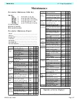
Maintenance
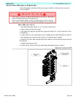
3.14 - Hydraulic Cylinder (Outrigger)
TL38 Service & Parts
I
NSTALLATION
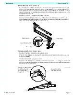
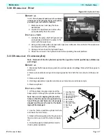
Note: before installing Upper Lift Cylinder check cylinder pins and bearings for wear and
replace if necessary.
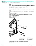
1. Lift the cylinder into place and insert the body end pin in through the cylinder and Second Post
Anchors.
Note: take care in aligning the pin in the holes so that the pin can be pushed in by hand. If
the pin and holes are not properly aligned and the pin is forced in, the bushings will be
damaged.
2. Line the Upper Boom Anchor holes up with the cylinder rod hole and insert the rod end pin.
(Note: To align the holes use an overhead crane and sling of suitable capacity firmly secured to
the Upper Boom at the cage end. This should be used to raise and lower the Upper Boom).
3. Slide both locking plates into the groves on the pins and secure with the bolts and washers.
4. Reconnect the hoses to their correct ports.
5. Test with weight at rated platform load to check system operation.
3.14 H
YDRAULIC
C
YLINDER
(O
UTRIGGER
)
R
EMOVAL
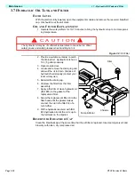
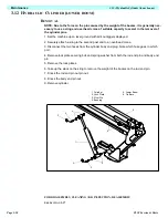
1. With the booms in the stowed position, raise all 4 outriggers.
2. Disconnect the hoses from the cylinder and plug to avoid excessive oil spillage, note which
hoses go to which port.
3. Remove the securing bolts and washers from the cylinder lock plates.
4. Remove the lock plates.
5. Holding the outrigger in position, knock out the body end pin.
6. Lower the outrigger and cylinder to the ground and knock out the rod end pin.
7. Remove the cylinder.
FOR DISASSEMBLY, CLEANING AND INSPECTION, REASSEMBLY
S
EE
S
ECTION
3-17
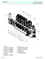
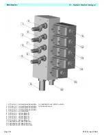
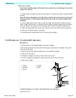
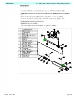
1. Cylinder
2. Lock Plate
3. Pivot Pin
4. Bushing
5. Outrigger
6. Washer
7. Bolt
1
2
3 & 4
6
5
7
3 & 4
2
6
7
Summary of Contents for TL38
Page 1: ...ERVICE PARTS MANUAL POWERED ACCESS WORK PLATFORM TL38 ...
Page 2: ......
Page 4: ......
Page 51: ...Page 3 28 Maintenance 3 17 Torque Specifications TL38 Service Parts NOTES ...
Page 59: ...Page 5 2 Schematics 5 1 Introduction TL38 Service Parts ...
Page 60: ...Page 5 3 Schematics 5 1 Introduction TL38 Service Parts ...
Page 61: ...Page 5 4 Schematics 5 1 Introduction TL38 Service Parts ...
Page 62: ...Page 5 5 Schematics 5 1 Introduction TL38 Service Parts ...
Page 63: ...Page 5 6 Schematics 5 1 Introduction TL38 Service Parts Notes ...
Page 66: ...Page 6 3 Illustrated Parts Breakdown General Assembly TL38 Service Parts ...
Page 70: ...Page 6 7 Illustrated Parts Breakdown Booms Posts Assembly TL38 Service Parts ...
Page 72: ...Page 6 9 Illustrated Parts Breakdown Platform Assembly TL38 Service Parts ...
Page 84: ...Page 6 21 Illustrated Parts Breakdown Outrigger Cylinder Assembly TL38 Service Parts NOTES ...
Page 86: ...Page 6 23 Illustrated Parts Breakdown Electrical Assembly TL38 Service Parts ...
Page 92: ...Page 6 29 Illustrated Parts Breakdown Decal Assembly TL38 Service Parts ...
Page 94: ...Page 6 31 Illustrated Parts Breakdown Decal Assembly TL38 Service Parts ...
Page 95: ...Page 6 32 Illustrated Parts Breakdown Decal Assembly TL38 Service Parts NOTES ...


