Page 3-8
Maintenance
3.6 - ECU options & Fault codes
TL38 Service & Parts
3.6 ECU
OPTIONS
& F
AULT
CODES
ECU O
PTIONS
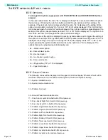
To change ECU options apply power with TELESCOPE/JIB and ROTATE BOOM buttons
pressed.
In the option adjust state, the code “AL” is displayed initially. There are several different options
that can be set. Pressing the right turn buttons scrolls through options and their settings. For
example, if the right turn button is pressed while the code “AL” is displayed, the setting of this
option, (motion alarm) is shown “On” for on or “OF” for off will be displayed. If the right turn but-
ton is pressed again, the code “Ad” will be displayed. If the right turn button is pressed again, the
setting of this option, (descent alarm) is shown “On” or “OF” will be displayed. The right turn but-
ton can be used to scroll through all the options and their settings.
When, the value of the option is displayed, pressing joystick enable switch toggles the setting of
the option. For example, if the joystick enable button is pressed while the setting value of “On” is
displayed, the setting of this option is changed to off and the display reads “OF”. If “OF” is dis-
played, pressing the joystick enable switch turns on the option and “On” is displayed. The
options that can be adjusted (each individually) are:
• AL – Motion alarm option
• Ad – Descent alarm option
• OL – Overload option
• 2H – two handed operation option
• dA – Drive assist option
• LI – Lift type option (“50” or “38” is displayed)
• Cr – Cage Rotate option
ECU F
AULT
C
ODES
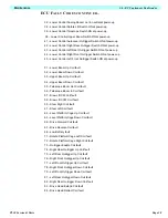
The following codes will be displayed on the upper control box display if there is a fault with a
machine componant or an in-valid command given to the ECU at system startup.
01 – System initialization error
02 – System communication error
03 – Platform Overload
04 – Ground Panel communication error
11 – Drive Assist Joystick Enable Switch ON at power-up
12 – Drive Assist Right Turn Switch ON at power-up
13 – Drive Assist Left Turn Switch ON at power-up
19 – Platform Cage Rotate Switch ON at power-up
21 – Platform Cage Level Switch ON at power-up
22 – Platform Left Turn Switch ON at power-up
23 – Platform Right Turn Switch ON at power-up
24 – Platform Rotate Lift Switch ON at power-up
26 – Platform Telescope Switch ON at power-up
27 – Platform Lower Boom Switch ON at power-up
28 – Platform Upper Boom Switch ON at power-up
29 – Platform Joystick Enable Switch ON at power-up
31 – Platform Joystick not in neutral at power-up
Summary of Contents for TL38
Page 1: ...ERVICE PARTS MANUAL POWERED ACCESS WORK PLATFORM TL38 ...
Page 2: ......
Page 4: ......
Page 51: ...Page 3 28 Maintenance 3 17 Torque Specifications TL38 Service Parts NOTES ...
Page 59: ...Page 5 2 Schematics 5 1 Introduction TL38 Service Parts ...
Page 60: ...Page 5 3 Schematics 5 1 Introduction TL38 Service Parts ...
Page 61: ...Page 5 4 Schematics 5 1 Introduction TL38 Service Parts ...
Page 62: ...Page 5 5 Schematics 5 1 Introduction TL38 Service Parts ...
Page 63: ...Page 5 6 Schematics 5 1 Introduction TL38 Service Parts Notes ...
Page 66: ...Page 6 3 Illustrated Parts Breakdown General Assembly TL38 Service Parts ...
Page 70: ...Page 6 7 Illustrated Parts Breakdown Booms Posts Assembly TL38 Service Parts ...
Page 72: ...Page 6 9 Illustrated Parts Breakdown Platform Assembly TL38 Service Parts ...
Page 84: ...Page 6 21 Illustrated Parts Breakdown Outrigger Cylinder Assembly TL38 Service Parts NOTES ...
Page 86: ...Page 6 23 Illustrated Parts Breakdown Electrical Assembly TL38 Service Parts ...
Page 92: ...Page 6 29 Illustrated Parts Breakdown Decal Assembly TL38 Service Parts ...
Page 94: ...Page 6 31 Illustrated Parts Breakdown Decal Assembly TL38 Service Parts ...
Page 95: ...Page 6 32 Illustrated Parts Breakdown Decal Assembly TL38 Service Parts NOTES ...

