Page 8
TL38 Service & Parts
Operation
L
O W E R I N G
T H E
P
L A T F O R M
1. Ensure the outriggers are deployed and the machine is level.
2. Select either the lower or upper boom lift function button (the button will illuminate to confirm selection).
3. While engaging the Interlock Switch, pull the Control Handle backwards.
4. If the machine is not level the tilt alarm will sound and the machine will not descend.
R
O T A T I N G
T H E
P
L A T F O R M
1. Ensure the outriggers are deployed and the machine is level.
2. Select the rotate function button (the button will illuminate to confirm selection).
3. While engaging the Interlock Switch, move the Control Handle forwards or backwards to achieve clock-
wise or counterclockwise rotation.
4. If the machine is not level the tilt alarm will sound and the machine will not rotate.
O
P E R A T I N G
T H E
J
I B
1. Ensure the outriggers are deployed and the machine is level.
2. Select jib function button (the button will illuminate to confirm selection).
3. While engaging the Interlock Switch, move the Control Handle forwards or backwards to jib out or jib in.
4. If the machine is not level the tilt alarm will sound and the machine will not telescope.
E
M E RG E N C Y
L
O W E R I N G
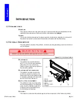
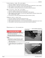
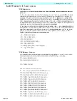
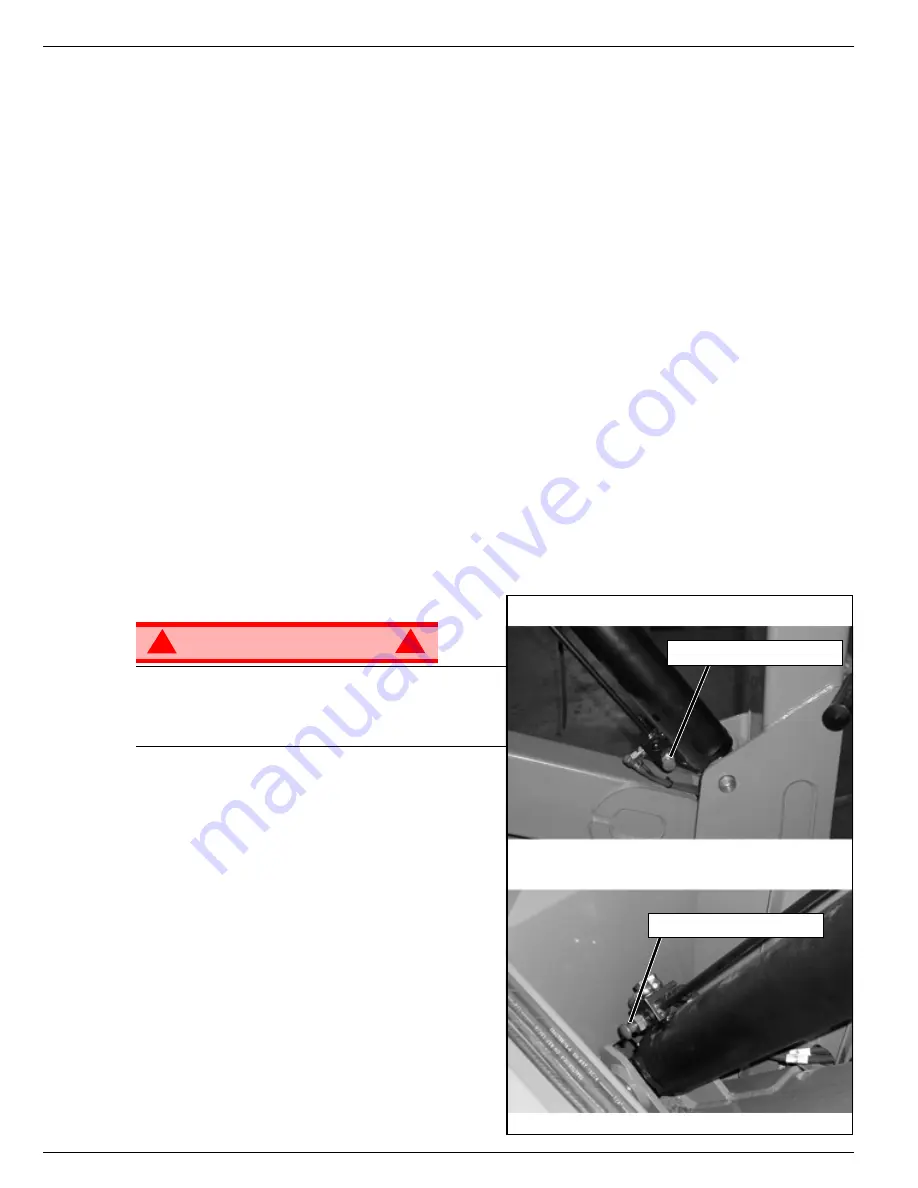
Figure 3:
Emergency Lowering Valve
W A R N I N G
!
!
If the platform should fail to lower, NEVER climb
down the elevating assembly.
Stand clear of the elevating assembly while
operating the Emergency Lowering Valve Knob.
TL38
The Emergency Lowering Valve for the TL38 is
located on the valve block of each lift cylinder.
1. Open the Emergency Lowering Valve by pushing
and holding the knob.
2. To close, release the knob. The platform will not
elevate if the Emergency Lowering Valve is
open.
Emergency Lowering Knob
Emergency Lowering Knob
Lower Boom
Upper Boom
Summary of Contents for TL38
Page 1: ...ERVICE PARTS MANUAL POWERED ACCESS WORK PLATFORM TL38 ...
Page 2: ......
Page 4: ......
Page 51: ...Page 3 28 Maintenance 3 17 Torque Specifications TL38 Service Parts NOTES ...
Page 59: ...Page 5 2 Schematics 5 1 Introduction TL38 Service Parts ...
Page 60: ...Page 5 3 Schematics 5 1 Introduction TL38 Service Parts ...
Page 61: ...Page 5 4 Schematics 5 1 Introduction TL38 Service Parts ...
Page 62: ...Page 5 5 Schematics 5 1 Introduction TL38 Service Parts ...
Page 63: ...Page 5 6 Schematics 5 1 Introduction TL38 Service Parts Notes ...
Page 66: ...Page 6 3 Illustrated Parts Breakdown General Assembly TL38 Service Parts ...
Page 70: ...Page 6 7 Illustrated Parts Breakdown Booms Posts Assembly TL38 Service Parts ...
Page 72: ...Page 6 9 Illustrated Parts Breakdown Platform Assembly TL38 Service Parts ...
Page 84: ...Page 6 21 Illustrated Parts Breakdown Outrigger Cylinder Assembly TL38 Service Parts NOTES ...
Page 86: ...Page 6 23 Illustrated Parts Breakdown Electrical Assembly TL38 Service Parts ...
Page 92: ...Page 6 29 Illustrated Parts Breakdown Decal Assembly TL38 Service Parts ...
Page 94: ...Page 6 31 Illustrated Parts Breakdown Decal Assembly TL38 Service Parts ...
Page 95: ...Page 6 32 Illustrated Parts Breakdown Decal Assembly TL38 Service Parts NOTES ...


