Page 3-12
Maintenance
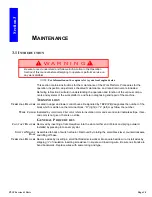
3.8 - Setting Hydraulic Pressures
TL38 Service & Parts
S
LEW
C
ROSS
-L
INE
R
ELIEF
VALVES
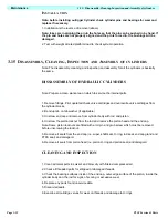
1. Operate the hydraulic system for 10-15 minutes to warm the oil.
2. Remove the cover from the 1st post.
3. Insert pressure gauge into high pressure gauge port marked ‘PT’ on top of front face of main
manifold block.
4. Loosen locknuts on both cross-line relief valves and turn adjusting screws counter clockwise
two full turns.
5. Operate slew function from lower controls and rotate elevating assembly through approx.
180
degrees
until the slew stop prevents further rotation.
6. Slowly turn the cross-line relief valve adjusting screw clockwise until the pressure gauge
reads 50 Bar pressure.
7. Now operate the slew function in the opposite direction through approx. 360
degrees
until
the slew
stop prevents further rotation.
8. Slowly turn the remaining cross-line relief valve adjusting screw clockwise until the pressure
gauge reads 50 Bar pressure.
9. Tighten the locknuts on both cross-line reief valves while holding the adjusting screws in posi-
tion.
Summary of Contents for TL38
Page 1: ...ERVICE PARTS MANUAL POWERED ACCESS WORK PLATFORM TL38 ...
Page 2: ......
Page 4: ......
Page 51: ...Page 3 28 Maintenance 3 17 Torque Specifications TL38 Service Parts NOTES ...
Page 59: ...Page 5 2 Schematics 5 1 Introduction TL38 Service Parts ...
Page 60: ...Page 5 3 Schematics 5 1 Introduction TL38 Service Parts ...
Page 61: ...Page 5 4 Schematics 5 1 Introduction TL38 Service Parts ...
Page 62: ...Page 5 5 Schematics 5 1 Introduction TL38 Service Parts ...
Page 63: ...Page 5 6 Schematics 5 1 Introduction TL38 Service Parts Notes ...
Page 66: ...Page 6 3 Illustrated Parts Breakdown General Assembly TL38 Service Parts ...
Page 70: ...Page 6 7 Illustrated Parts Breakdown Booms Posts Assembly TL38 Service Parts ...
Page 72: ...Page 6 9 Illustrated Parts Breakdown Platform Assembly TL38 Service Parts ...
Page 84: ...Page 6 21 Illustrated Parts Breakdown Outrigger Cylinder Assembly TL38 Service Parts NOTES ...
Page 86: ...Page 6 23 Illustrated Parts Breakdown Electrical Assembly TL38 Service Parts ...
Page 92: ...Page 6 29 Illustrated Parts Breakdown Decal Assembly TL38 Service Parts ...
Page 94: ...Page 6 31 Illustrated Parts Breakdown Decal Assembly TL38 Service Parts ...
Page 95: ...Page 6 32 Illustrated Parts Breakdown Decal Assembly TL38 Service Parts NOTES ...

