Page 3-20
Maintenance
3.13 - Hydraulic Cylinder (Upper boom)
TL38 Service & Parts
3.13 H
YDRAULIC
C
YLINDER
(U
PPER
BOOM
)
R
EMOVAL
NOTE: Due to the force on the pins caused by the weight of the booms, it is generally nec-
essary to use a sling and overhead crane of suitable capacity to assist in the removal of
the cylinder pins.
1. Set the machine up on level ground with all 4 outriggers deployed.
2. Securely attach a sling to the Upper Boom (platform end) and to an overhead crane.
3. Disconnect the two hoses from the cylinder body and plug. Note which hose goes to which
port.
4. Remove lock plate securing bolt and spring washer from both the rod end pin and body end
pin.
5. Remove the lock plates.
6. Take up the slack on the sling to remove the weight of the booms on the rod end pin.
7. Knock the rod end pin out pin out.
8. Knock the body end pin out.
9. Remove cylinder.
FOR DISASSEMBLY, CLEANING AND INSPECTION, REASSEMBLY
S
EE
S
ECTION
3-17
1
2
3
4
5
6
7
4
7
3
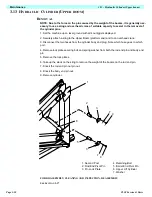
1. Second Post
2. Rod End Pivot Pin
3. Pin Lock Plate
4. Retaining Bolt
5. Barrel End Pivot Pin
6. Upper Lift Cylinder
7. Washer
Summary of Contents for TL38
Page 1: ...ERVICE PARTS MANUAL POWERED ACCESS WORK PLATFORM TL38 ...
Page 2: ......
Page 4: ......
Page 51: ...Page 3 28 Maintenance 3 17 Torque Specifications TL38 Service Parts NOTES ...
Page 59: ...Page 5 2 Schematics 5 1 Introduction TL38 Service Parts ...
Page 60: ...Page 5 3 Schematics 5 1 Introduction TL38 Service Parts ...
Page 61: ...Page 5 4 Schematics 5 1 Introduction TL38 Service Parts ...
Page 62: ...Page 5 5 Schematics 5 1 Introduction TL38 Service Parts ...
Page 63: ...Page 5 6 Schematics 5 1 Introduction TL38 Service Parts Notes ...
Page 66: ...Page 6 3 Illustrated Parts Breakdown General Assembly TL38 Service Parts ...
Page 70: ...Page 6 7 Illustrated Parts Breakdown Booms Posts Assembly TL38 Service Parts ...
Page 72: ...Page 6 9 Illustrated Parts Breakdown Platform Assembly TL38 Service Parts ...
Page 84: ...Page 6 21 Illustrated Parts Breakdown Outrigger Cylinder Assembly TL38 Service Parts NOTES ...
Page 86: ...Page 6 23 Illustrated Parts Breakdown Electrical Assembly TL38 Service Parts ...
Page 92: ...Page 6 29 Illustrated Parts Breakdown Decal Assembly TL38 Service Parts ...
Page 94: ...Page 6 31 Illustrated Parts Breakdown Decal Assembly TL38 Service Parts ...
Page 95: ...Page 6 32 Illustrated Parts Breakdown Decal Assembly TL38 Service Parts NOTES ...

